
Installation Instructions
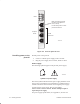

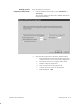
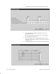
Table Of Contents
- Title page
- Contents
- About this manual
- Safety information
- Ch 1 - Introduction
- Ch 2 - Adding cards to the Controller
- Unpacking the System Controller
- Unpacking the picocells
- System Controller card configuration
- Adding cards to the System Controller (first steps)
- Jumper and DIP switch settings
- Attaching bus cables
- Adding cards to the System Controller (final steps)
- Configuring Controller cards
- Verifying the card configuration
- Ch 3 - Installing the Controller
- Ch 4 - Verifying the Controller configuration
- Ch 5 - Configuring the router
- Ch 6 - Testing picocells
- Ch 7 - Installing picocells
- Ch 8 - Connecting to external equipment
- Ch 9 - System testing
- Ch 10 - Installation inspection
- Ch 11 - Provisioning
- Ch 12 - Remote Client
- Ch 13 - Troubleshooting
- Ch 14 - Maintaining Quad T1 cards
- App A - Specifications
- App B - Standards compliance information
- App C - Part numbers
- App D - Updates and backups
- Index

1026209–0001 Revision B
Testing picocells 6–5
Power on the picocell, and observe the picocell LEDs as the
System Controller automatically downloads software to the
picocell:
1. Press the picocell power switch to the LINE (line power)
position.
2. Observe the LEDs for normal operation:
a. During software loading, the Temp LED on the front
of the picocell is orange. See Figure 6-3.
b. When the picocell is fully loaded and operational, the
Power and Temp LEDs display green, and the Alarm
LED is off.
T0001003
Power
Green - Voltage normal
Orange - Low voltage
Alarm (Controller)
Off - Normal
Orange - Minor alarm
Red - Major alarm
Temperature (power supply)
Green - Normal
Red - Exceeds 75° C
Power
Te mp
Alarm
Alarm LED is orange while
the Controller boots.
Figure 6-3 LEDs on front of picocell
Note
The LED information above is for production picocells. LED
codes may be different for pre–production picocells.
6.2
Verifying software
load