
Installation Instructions
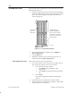
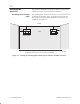
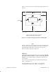
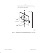
Table Of Contents
- Title page
- Contents
- About this manual
- Safety information
- Ch 1 - Introduction
- Ch 2 - Adding cards to the Controller
- Unpacking the System Controller
- Unpacking the picocells
- System Controller card configuration
- Adding cards to the System Controller (first steps)
- Jumper and DIP switch settings
- Attaching bus cables
- Adding cards to the System Controller (final steps)
- Configuring Controller cards
- Verifying the card configuration
- Ch 3 - Installing the Controller
- Ch 4 - Verifying the Controller configuration
- Ch 5 - Configuring the router
- Ch 6 - Testing picocells
- Ch 7 - Installing picocells
- Ch 8 - Connecting to external equipment
- Ch 9 - System testing
- Ch 10 - Installation inspection
- Ch 11 - Provisioning
- Ch 12 - Remote Client
- Ch 13 - Troubleshooting
- Ch 14 - Maintaining Quad T1 cards
- App A - Specifications
- App B - Standards compliance information
- App C - Part numbers
- App D - Updates and backups
- Index

1026209–0001 Revision B 6–24 Testing picocells
The procedures below explain how to test all transceivers in each
installed traffic picocell.
1. Determine which picocell slots contain transceivers (BTCs).
A label attached to the picocell tells you which slots contain
BTCs. The slot arrangement and numbering scheme are
shown in Figure 6-5.
1
0
2
3
4
CPU
The CPU
slot is not
numbered.
Depending on the
picocell configuration,
slots 0 - 4 may contain
2 to 4 BTCs, a scanning
receiver or some slots
may be empty.
–
T0001032
Figure 6-5 Picocell slot numbers
2. From the AIReach Office Window, select Configure →
BSC Configuration.
3. Click the BTSs tab.
4. Highlight and double–click on the traffic picocell to be
tested, and click the BTS Components tab.
Test the first transceiver (any one) as follows:
1. Leave the transceiver to be tested in service (INS). Take all
other transceivers (BTCs) out of service (OOS).
a. For each slot that contains a BTC:
i. Select BTC from the Hardware Type
dropdown list.
ii. Select OOS from the Desired State dropdown
list.
b. Click Accept.
The software displays the AROSC Configuration
window.
2. Record the power level displayed on the test mobiles.
3. Initiate a mobile–to–mobile test call. (Dial the 4–digit LDN
assigned to the other test mobile.)
6.9
Placing test calls
First transceiver test