
Installation Instructions
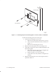
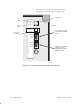
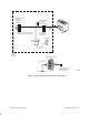
Table Of Contents
- Title page
- Contents
- About this manual
- Safety information
- Ch 1 - Introduction
- Ch 2 - Adding cards to the Controller
- Unpacking the System Controller
- Unpacking the picocells
- System Controller card configuration
- Adding cards to the System Controller (first steps)
- Jumper and DIP switch settings
- Attaching bus cables
- Adding cards to the System Controller (final steps)
- Configuring Controller cards
- Verifying the card configuration
- Ch 3 - Installing the Controller
- Ch 4 - Verifying the Controller configuration
- Ch 5 - Configuring the router
- Ch 6 - Testing picocells
- Ch 7 - Installing picocells
- Ch 8 - Connecting to external equipment
- Ch 9 - System testing
- Ch 10 - Installation inspection
- Ch 11 - Provisioning
- Ch 12 - Remote Client
- Ch 13 - Troubleshooting
- Ch 14 - Maintaining Quad T1 cards
- App A - Specifications
- App B - Standards compliance information
- App C - Part numbers
- App D - Updates and backups
- Index

1026209–0001 Revision B 7–6 Installing picocell
G-17414 F
10/04/99
Mounting plate
Four fasteners
This side up
1
2
3
4
Figure 7-4 Attaching the picocell mounting plate to concrete, block, or wallboard
To attach the mounting plate (for all wall types):
1. Position the mounting plate on the wall:
a. Make sure the part labeled “This side up” is on top.
b. Allow at least the minimum clearance, as shown in
Figure 7-1.
c. Make sure the mounting plate is level.
2. Mark on the wall the position of each mounting screw.
3. If the cable to the picocell will be installed through the wall
and mounting plate:
a. Mark on the wall the outline of the rectangular hole
in the center of the mounting plate.
b. Remove the plate so you can cut the hole.
c. Cut the hole in the wall, inside the rectangular wall
marking.
4. Mount the mounting plate on the wall using the fasteners
specified in Table 7-1 .