
Installation Instructions
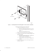
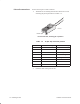
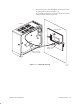
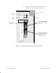
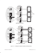
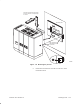
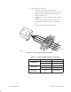
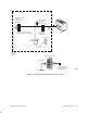
Table Of Contents
- Title page
- Contents
- About this manual
- Safety information
- Ch 1 - Introduction
- Ch 2 - Adding cards to the Controller
- Unpacking the System Controller
- Unpacking the picocells
- System Controller card configuration
- Adding cards to the System Controller (first steps)
- Jumper and DIP switch settings
- Attaching bus cables
- Adding cards to the System Controller (final steps)
- Configuring Controller cards
- Verifying the card configuration
- Ch 3 - Installing the Controller
- Ch 4 - Verifying the Controller configuration
- Ch 5 - Configuring the router
- Ch 6 - Testing picocells
- Ch 7 - Installing picocells
- Ch 8 - Connecting to external equipment
- Ch 9 - System testing
- Ch 10 - Installation inspection
- Ch 11 - Provisioning
- Ch 12 - Remote Client
- Ch 13 - Troubleshooting
- Ch 14 - Maintaining Quad T1 cards
- App A - Specifications
- App B - Standards compliance information
- App C - Part numbers
- App D - Updates and backups
- Index

1026209–0001 Revision B 7–8 Installing picocell
Connect the T1/power cable as follows:
1. Terminate the T1 cable(s) with RJ–45 connectors on each
end using the pinout plan shown in Table 7-2 .
Plastic clip
Pin 1
T0002001
RJ–45 connector, showing pin 1 position
Table 7-2 T1 (RJ–45) connector pinouts
Pin T1 connector signal CAT 5 color coding
1 RX RING White–blue
2 RX TIP Blue–white
3 +VDC1 (GND) White–green
4 TX RING White–orange
5 TX TIP Orange–white
6 –VDC1 Green–white
7 +VDC2 (GND) White–brown
8 –VDC2 Brown–white
2. Label the cable at the picocell end.
Picocell connections