
Installation Instructions
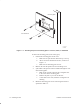
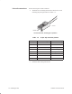
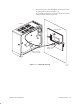
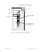
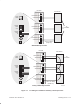
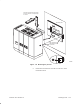
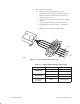
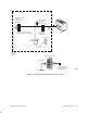
Table Of Contents
- Title page
- Contents
- About this manual
- Safety information
- Ch 1 - Introduction
- Ch 2 - Adding cards to the Controller
- Unpacking the System Controller
- Unpacking the picocells
- System Controller card configuration
- Adding cards to the System Controller (first steps)
- Jumper and DIP switch settings
- Attaching bus cables
- Adding cards to the System Controller (final steps)
- Configuring Controller cards
- Verifying the card configuration
- Ch 3 - Installing the Controller
- Ch 4 - Verifying the Controller configuration
- Ch 5 - Configuring the router
- Ch 6 - Testing picocells
- Ch 7 - Installing picocells
- Ch 8 - Connecting to external equipment
- Ch 9 - System testing
- Ch 10 - Installation inspection
- Ch 11 - Provisioning
- Ch 12 - Remote Client
- Ch 13 - Troubleshooting
- Ch 14 - Maintaining Quad T1 cards
- App A - Specifications
- App B - Standards compliance information
- App C - Part numbers
- App D - Updates and backups
- Index

1026209–0001 Revision B 7–14 Installing picocell
6. Set up the power connection:
a. Mount the power supply in the telco room.
Typically, the power supply is mounted to plywood.
b. Remove the DIN connector from the power wire.
c. Strip the end of the wire.
d. Clip the green wire (not used), fold it back, and heat
shrink it.
e. Connect the wires from the power supply to the
terminal block, as shown in Figure 7-9 and Table
7-3 .
f. Plug the power cable into a 110 Vac outlet.
Figure 7-9 Power terminal block connections
CAT 5
Power
supply
G-17404 F
08/24/99
To picocell
Table 7-3 Power supply and CAT 5 wire colors
Power supply wire Cat 5 wire
48 Vdc load
White Green–white
–48 Vdc load
Black Brown–white
48 Vdc return
Red White–green
–48 Vdc return
Brown White–brown
AC ground
(not used)
Green Not applicable