
Installation Instructions
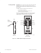
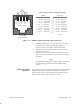
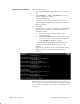
Table Of Contents
- Title page
- Contents
- About this manual
- Safety information
- Ch 1 - Introduction
- Ch 2 - Adding cards to the Controller
- Unpacking the System Controller
- Unpacking the picocells
- System Controller card configuration
- Adding cards to the System Controller (first steps)
- Jumper and DIP switch settings
- Attaching bus cables
- Adding cards to the System Controller (final steps)
- Configuring Controller cards
- Verifying the card configuration
- Ch 3 - Installing the Controller
- Ch 4 - Verifying the Controller configuration
- Ch 5 - Configuring the router
- Ch 6 - Testing picocells
- Ch 7 - Installing picocells
- Ch 8 - Connecting to external equipment
- Ch 9 - System testing
- Ch 10 - Installation inspection
- Ch 11 - Provisioning
- Ch 12 - Remote Client
- Ch 13 - Troubleshooting
- Ch 14 - Maintaining Quad T1 cards
- App A - Specifications
- App B - Standards compliance information
- App C - Part numbers
- App D - Updates and backups
- Index

1026209–0001 Revision B 7–16 Installing picocell
Important: All T1 wiring must comply with TIA/EIA–568A and
TIA/EIA–606. (In Canada, T1 wiring must comply with CSA
Standards T528 and T529.) These standards are listed in Appendix
B, Section B.5.
A T568B–compliant wiring flip must be used between:
• The Controller and picocell
• Daisy–chained picocells (that is, between each
picocell–to–picocell connection)
The flip is accomplished at the patch panel (as shown in Figure
7-11) or using a modular jack (Figure 7-12). The flip must be
T568B compliant, as shown in these two illustrations.
T0001021
White/Green
Green/White
White/Brown
Brown/White
White/Blue
Blue/White
White/Orange
Orange/White
Side view
Rear view
(flip detail, T568B)
Patch
panel
RJ-45
connector,
straight through
Patch
panel
Flip
To
picocell
Figure 7-11 T568B–compliant wiring flip at patch panel
T1 wiring and flip