
Installation Instructions
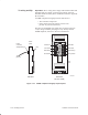
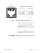
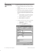
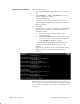
Table Of Contents
- Title page
- Contents
- About this manual
- Safety information
- Ch 1 - Introduction
- Ch 2 - Adding cards to the Controller
- Unpacking the System Controller
- Unpacking the picocells
- System Controller card configuration
- Adding cards to the System Controller (first steps)
- Jumper and DIP switch settings
- Attaching bus cables
- Adding cards to the System Controller (final steps)
- Configuring Controller cards
- Verifying the card configuration
- Ch 3 - Installing the Controller
- Ch 4 - Verifying the Controller configuration
- Ch 5 - Configuring the router
- Ch 6 - Testing picocells
- Ch 7 - Installing picocells
- Ch 8 - Connecting to external equipment
- Ch 9 - System testing
- Ch 10 - Installation inspection
- Ch 11 - Provisioning
- Ch 12 - Remote Client
- Ch 13 - Troubleshooting
- Ch 14 - Maintaining Quad T1 cards
- App A - Specifications
- App B - Standards compliance information
- App C - Part numbers
- App D - Updates and backups
- Index

1026209–0001 Revision B 8–2 Connecting to external equipment
To establish final System Controller connectivity, connect the
Controller to the PBX and connect the analog line as follows:
1. Terminate the PBX T1 trunk CAT 5 cable with a RJ–45
connector.
2. Connect the PBX T1 trunk to port 1 of the assigned Quad
T1 card.
3. Verify that the Controller configuration values indicated
below are set to the values specified in the (customer
site–specific) AIReach OS Configuration Report. If any
values are not as specified, change them to the specified
values.
a. System Capability – For instructions concerning
System Capability configuration, see page 4–17.
b. Transport configuration – See page 4–18.
c. MSC Configuration – See page 4–19.
d. HLR Configuration – See page 4–21.
4. Configure the link between the Controller and the PBX:
a. On the Controller, click Start → Settings →
Control Panel.
b. Double–click the System icon.
c. Click the Environment tab (shown below).
8.1
Connecting the
Controller to the
PBX