
Installation Instructions
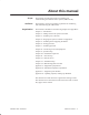
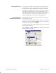


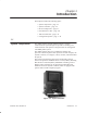
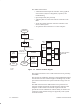
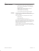
Table Of Contents
- Title page
- Contents
- About this manual
- Safety information
- Ch 1 - Introduction
- Ch 2 - Adding cards to the Controller
- Unpacking the System Controller
- Unpacking the picocells
- System Controller card configuration
- Adding cards to the System Controller (first steps)
- Jumper and DIP switch settings
- Attaching bus cables
- Adding cards to the System Controller (final steps)
- Configuring Controller cards
- Verifying the card configuration
- Ch 3 - Installing the Controller
- Ch 4 - Verifying the Controller configuration
- Ch 5 - Configuring the router
- Ch 6 - Testing picocells
- Ch 7 - Installing picocells
- Ch 8 - Connecting to external equipment
- Ch 9 - System testing
- Ch 10 - Installation inspection
- Ch 11 - Provisioning
- Ch 12 - Remote Client
- Ch 13 - Troubleshooting
- Ch 14 - Maintaining Quad T1 cards
- App A - Specifications
- App B - Standards compliance information
- App C - Part numbers
- App D - Updates and backups
- Index

1026209–0001 Revision B 1–2 Introduction
The AIReach OS features:
• A Windows NT based System Controller with a graphical
user interface (GUI) for configuration, operation, and
troubleshooting
• Up to 64 picocells (line powered)
• A Primary Rate T1 connection from the Controller to the
PBX
• An IS–41 TCP/IP connection from the Controller to the
macro cellular system
• An optional LAN connection to a remote computer.
Controller
Alarm
printer
Remote
workstation
Corporate
LAN
56K leased line
Patch
panel
Router
DSU
PBX
PSTN
IS-4I
gateway
MACRO
Picocell
Picocell
Picocell
CAT-5
T1
CAT-5
T1
CAT-5
T1
Picocell
PicocellPicocell
T1
T1
G-17007 F
11/05/99
Daisy-chained
picocells
10BaseT
TCP/IP IS-41
CAT-5 T1
ISDN PRI
Figure 1-2 AIReach OS block diagram
The System Controller is rack or table mounted in close proximity
to the PBX.
The picocells are small Base Transceiver Stations (BTSs) designed
to be mounted on office walls throughout a building. They are line
powered and connected to the System Controller using CAT 5 T1
cables.
The OMC functions of the AIReach OS can be performed at a
specially configured (customer provided) remote computer. This
computer can be located on an internal corporate LAN and
provide the network administrator with the ability to monitor and
control the system without having to be physically at the System
Controller location.