
Installation Instructions
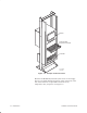

Table Of Contents
- Title page
- Contents
- About this manual
- Safety information
- Ch 1 - Introduction
- Ch 2 - Adding cards to the Controller
- Unpacking the System Controller
- Unpacking the picocells
- System Controller card configuration
- Adding cards to the System Controller (first steps)
- Jumper and DIP switch settings
- Attaching bus cables
- Adding cards to the System Controller (final steps)
- Configuring Controller cards
- Verifying the card configuration
- Ch 3 - Installing the Controller
- Ch 4 - Verifying the Controller configuration
- Ch 5 - Configuring the router
- Ch 6 - Testing picocells
- Ch 7 - Installing picocells
- Ch 8 - Connecting to external equipment
- Ch 9 - System testing
- Ch 10 - Installation inspection
- Ch 11 - Provisioning
- Ch 12 - Remote Client
- Ch 13 - Troubleshooting
- Ch 14 - Maintaining Quad T1 cards
- App A - Specifications
- App B - Standards compliance information
- App C - Part numbers
- App D - Updates and backups
- Index

1026209–0001 Revision B
Introduction 1–7
The picocell consists of a backplane covered by an external
housing and contains the following internal components:
• Master oscillator: Provides a reference frequency for
picocell signal timing.
• Power supply: Converts the –48 Vdc input power to –6.5
Vdc for internal picocell operation.
• Transceivers: Each traffic picocell includes up to four
transceivers, with each transceiver providing three full–rate
TDMA channels. One channel is used as the digital control
channel (DCCH) to provide access information to the
mobiles. The remaining full–rate channels are used as
digital traffic channels (DTC). Each picocell can handle 11
mobile voice channels simultaneously, when fully loaded.
Each mobile phone requires one voice channel.
Transceivers are used only in traffic picocells.
• Scanning receiver: This module is used in scanning or
traffic picocells to monitor the transmitter signal strength of
the neighboring base stations. One scanner (maximum) is
used per scanning picocell.
• Picocell Controller: This module is the processor of the
picocell. It configures and controls the transceivers
operation using a proprietary protocol via the ST–BUS. The
Picocell controller uses one T1 slot to communicate with
the System Controller. The remaining slots are used to
provide bearer services.
• Antenna and branching module: The transmit and
diversity receivers of the installed transceivers are
combined and split in this module. The picocell has a 360°
omnidirectional radiation pattern in azimuth.
• Locking tab, lock, and key: The lock and key secure the
picocell to the locking tab on the mounting plate.
• Mounting plate: To ensure secure mounting, the installer
attaches a mounting plate to the wall, and then mounts the
picocell to the mounting plate.
1.3
Picocell
components