
Installation Instructions
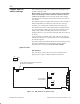
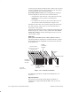
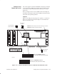
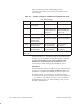
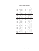
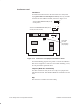
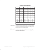
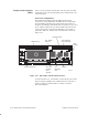
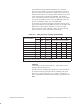
Table Of Contents
- Title page
- Contents
- About this manual
- Safety information
- Ch 1 - Introduction
- Ch 2 - Adding cards to the Controller
- Unpacking the System Controller
- Unpacking the picocells
- System Controller card configuration
- Adding cards to the System Controller (first steps)
- Jumper and DIP switch settings
- Attaching bus cables
- Adding cards to the System Controller (final steps)
- Configuring Controller cards
- Verifying the card configuration
- Ch 3 - Installing the Controller
- Ch 4 - Verifying the Controller configuration
- Ch 5 - Configuring the router
- Ch 6 - Testing picocells
- Ch 7 - Installing picocells
- Ch 8 - Connecting to external equipment
- Ch 9 - System testing
- Ch 10 - Installation inspection
- Ch 11 - Provisioning
- Ch 12 - Remote Client
- Ch 13 - Troubleshooting
- Ch 14 - Maintaining Quad T1 cards
- App A - Specifications
- App B - Standards compliance information
- App C - Part numbers
- App D - Updates and backups
- Index

1026209–0001 Revision B 2–18 Adding cards to the System Controller
I/O address
I/O address 0x2140 is used for the first conference card (in slot
13). If you install a second conference card (in slot 14), use DIP
switch S1 to select address 0x2160, as shown in Figure 2-12.
T0001016
JP3
JP4
1
S1
4
ON
14
ON
14
ON
Leave JP3
and JP4
unconnected
(no jumpers).
Address for :
0x2140 all OFF)
first conference card
(
(slot 13)
Address for (slot 14)second conference card :
0x2160 (OFF, OFF, OFF, ON)
Figure 2-12 Conference card jumpers and address switch
For troubleshooting purposes only, Table 2-3 shows all addresses
that can be assigned to a conference card. When installing a card,
use only the address specified above.
Jumpers (MVIP bus termination)
For either conference card (in slot 13 or 14), leave jumpers JP3
and JP4 unconnected. This disables MVIP bus termination for the
card.
IRQ
The conference card does not need an IRQ.
Conference card