
Installation Instructions
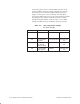
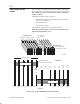

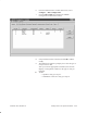
Table Of Contents
- Title page
- Contents
- About this manual
- Safety information
- Ch 1 - Introduction
- Ch 2 - Adding cards to the Controller
- Unpacking the System Controller
- Unpacking the picocells
- System Controller card configuration
- Adding cards to the System Controller (first steps)
- Jumper and DIP switch settings
- Attaching bus cables
- Adding cards to the System Controller (final steps)
- Configuring Controller cards
- Verifying the card configuration
- Ch 3 - Installing the Controller
- Ch 4 - Verifying the Controller configuration
- Ch 5 - Configuring the router
- Ch 6 - Testing picocells
- Ch 7 - Installing picocells
- Ch 8 - Connecting to external equipment
- Ch 9 - System testing
- Ch 10 - Installation inspection
- Ch 11 - Provisioning
- Ch 12 - Remote Client
- Ch 13 - Troubleshooting
- Ch 14 - Maintaining Quad T1 cards
- App A - Specifications
- App B - Standards compliance information
- App C - Part numbers
- App D - Updates and backups
- Index

1026209–0001 Revision B 2–22 Adding cards to the System Controller
Connect JP2 pins 2 and 3 for normal CMOS operation. In the
event that CMOS settings prevent the AIReach OS Controller
from booting, you can clear the CMOS settings by placing a
jumper over JP2 pins 1 and 2. Do this only in an emergency.
Clearing the CMOS helps correct only certain hardware problems.
Operating system or software problems cannot be remedied
through clearing the CMOS. If it is necessary to clear CMOS
settings, see HNS document 1027630 for the proper settings.
Table 2-5 SBC card jumper settings
Use these settings.
Jumper Function Setting
J17 Watchdog timer Enabled ON
JP2 Normal CMOS
operation
Normal operation Connect pins
2–3
JP3 Watchdog timer
pre–timeout
interrupt option
Disabled Connect pins
2–3
JP4 PnP and BIOS
flash upgrade
Enabled Connect pins
2–3