
Installation Instructions
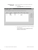
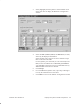
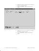
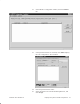
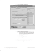
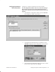
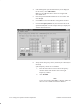
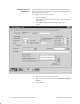
Table Of Contents
- Title page
- Contents
- About this manual
- Safety information
- Ch 1 - Introduction
- Ch 2 - Adding cards to the Controller
- Unpacking the System Controller
- Unpacking the picocells
- System Controller card configuration
- Adding cards to the System Controller (first steps)
- Jumper and DIP switch settings
- Attaching bus cables
- Adding cards to the System Controller (final steps)
- Configuring Controller cards
- Verifying the card configuration
- Ch 3 - Installing the Controller
- Ch 4 - Verifying the Controller configuration
- Ch 5 - Configuring the router
- Ch 6 - Testing picocells
- Ch 7 - Installing picocells
- Ch 8 - Connecting to external equipment
- Ch 9 - System testing
- Ch 10 - Installation inspection
- Ch 11 - Provisioning
- Ch 12 - Remote Client
- Ch 13 - Troubleshooting
- Ch 14 - Maintaining Quad T1 cards
- App A - Specifications
- App B - Standards compliance information
- App C - Part numbers
- App D - Updates and backups
- Index
1026209–0001 Revision B
Verifying the System Controller configuration 4–13
6. Click Close to return to the AROSC Configuration window.
The scanning picocell you added should now be listed.
7. Click Add to display the Cell Configuration – New
window.
8. Enter the required data for a traffic picocell.
9. Click the Cell DCCH tab. Verify the information displayed.
10. Click the Cell Handoff tab. Verify the information
displayed.
11. Click the Cell Physical Layer tab. Verify the information
displayed.
12. Click the Cell RRM tab. Verify the information displayed.
13. Click Close to return to the AROSC Configuration window.
If you made changes, the software prompts you to accept
them.
14.
Repeat steps 7 through 13 until all traffic picocells are
listed in the AROSC Configuration window (Cell tab).