HN System Installation Manual for .
Copyright © 2007 Hughes Network Systems, LLC All rights reserved. This publication and its contents are proprietary to Hughes Network Systems, LLC. No part of this publication may be reproduced in any form or by any means without the written permission of Hughes Network Systems, LLC, 11717 Exploration Lane, Germantown, Maryland 20876. Hughes Network Systems, LLC has made every effort to ensure the correctness and completeness of the material in this document.
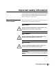
Important safety information For your safety and protection, read this entire installation manual before you attempt to install the satellite antenna. In particular, read this safety section carefully. Keep this safety information where you can refer to it if necessary. Types of warnings used in this manual This section introduces the various types of warnings used in this manual to alert you to possible safety hazards.
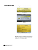
Product warning labels The following safety alert labels are affixed to the satellite antenna feed support tube, transmitter, and antenna reflector: Feed support tube Transmitter Reflector (back side) Safety alert labels on the antenna assembly These labels advise that the antenna emits radio frequency (RF) energy. Because of this potential safety hazard, observe all cautions on these labels and in the following section (Antenna installation safety) concerning RF radiation.
Antenna installation safety Observe the following precautions when installing the satellite antenna. This manual also includes additional safety alerts where appropriate concerning specific installation procedures. WARNING Only Hughes-certified installers may install or service Hughes earth stations and components. Installers must expressly acknowledge the Hughes requirements for Hughes installations.
WARNING • Do not work in high wind or rain or if a storm, lightning, or other adverse weather conditions are present or approaching. • Do not attempt to assemble, move, or mount the antenna on a windy day. Even a slight wind can unexpectedly create strong, unexpected forces on the antenna surface.
CAUTION Observe these precautions to avoid exposure to RF radiation, a potential safety hazard: • The antenna must be installed in a location or manner not readily accessible to children and in a manner that prevents human exposure to potentially harmful levels of radiation.
CAUTION • All installations of any type or size must carry an industry standard and government approved Radiation Hazard Caution label on the feed arm. • A fenced or roof installation in a commercial, industrial, or institutional environment must carry a Radiation Hazard Caution sign on the access door, gate, or permanently mounted access ladder that is within plain sight of anyone approaching the antenna from the front or sides of the reflector.
Contents Important safety information . . . . . . . . . . . . . . . . . . . . . iii Types of warnings used in this manual . . . . . . . . . . . . . . . . . . . iii Product warning labels . . . . . . . . . . . . . . . . . . . . . . . . . . . . . . . . iv Antenna installation safety . . . . . . . . . . . . . . . . . . . . . . . . . . . . . .v About this document . . . . . . . . . . . . . . . . . . . . . . . . . . xvii Scope and audience . . . . . . . . . . . . . . . . . . . . . . . . . . . . . . . . .
Small hardware parts lists. . . . . . . . . . . . . . . . . . . . . . . . . . . . . .18 Additional parts for J-type radio. . . . . . . . . . . . . . . . . . . . . . .19 Tools . . . . . . . . . . . . . . . . . . . . . . . . . . . . . . . . . . . . . . . . . . . . . .20 Chapter 3 Assembling the antenna. . . . . . . . . . . . . . . . . . . . . . . . . .21 Determining the pointing values . . . . . . . . . . . . . . . . . . . . . . . .21 General instructions for assembling the antenna . . . . . . . . . . . .
Chapter 7 Pointing the antenna . . . . . . . . . . . . . . . . . . . . . . . . . . . .55 Antenna pointing overview . . . . . . . . . . . . . . . . . . . . . . . . . . . .56 Using the installation software . . . . . . . . . . . . . . . . . . . . . . . .56 Peaking the signal (description) . . . . . . . . . . . . . . . . . . . . . . .56 Personnel requirements . . . . . . . . . . . . . . . . . . . . . . . . . . . . .57 Pointing parameters . . . . . . . . . . . . . . . . . . . . . . . . . . . . . . . .
xii • Contents 1037312-0001 Revision A
Figures Chapter 1 1. Hughes model AN6-098P .98 m satellite antenna with radio . . . . . . . . . . . . . . .2 Chapter 2 2. Shipping container contents—main components . . . . . . . . . . . . . . . . . . . . . . . . .9 3. Az/El and reflector bracket assembly (pre-assembled as one unit) . . . . . . . . . .10 4. Antenna reflector . . . . . . . . . . . . . . . . . . . . . . . . . . . . . . . . . . . . . . . . . . . . . . . .11 5. Feed support tubes (two types) . . . . . . . . . . . . . . . . . . . . . . . . . .
31. Securing the feed horn clamp . . . . . . . . . . . . . . . . . . . . . . . . . . . . . . . . . . . . . . .39 32. Attaching the radio assembly to the feed support tube. . . . . . . . . . . . . . . . . . . .40 33. Attaching the radio assembly to the feed support tube. . . . . . . . . . . . . . . . . . . .41 Chapter 5 34. Attaching the feed horn and radio assembly . . . . . . . . . . . . . . . . . . . . . . . . . . .44 35. O-ring in groove . . . . . . . . . . . . . . . . . . . . . . . . . . . . . . . . .
Tables Chapter 2 1. Two antenna kit configurations . . . . . . . . . . . . . . . . . . . . . . . . . . . . . . . . . . . . . .8 2. Small hardware parts used in antenna kits for both radio types . . . . . . . . . . . . .18 3. Additional small hardware parts included in the antenna kit for the J-type radio assembly . . . . . . . . . . . . . . . . . . . . . . . . . . . . . . . . . . . . . . . . . . . . .19 4. Tools required to install and point the antenna. . . . . . . . . . . . . . . . . . . . . . . . . .
xvi • Tables 1037312-0001 Revision A
About this document Scope and audience This manual explains how to assemble, install, and point the Hughes model AN6-098P .98 m antenna. It is written for qualified installers who are familiar with satellite antenna installation practices and are capable of properly applying the information presented.
Related publications The HN System Antenna Site Preparation and Mount Installation Guide (1035678-0001) contains detailed information about: • • • • • Safety considerations for mount and antenna installations Site surveys Trimasts and other types of antenna mounts Antenna installations on various types of surfaces Requirements for antennas that will be used in a Ka-band system or will later be upgraded for use in a Ka-band system Additional related publications are identified in Tasks related to antenna
Chapter 1 Overview This chapter presents an overview of the Hughes model AN6-098P .
The model AN6-098P antenna Each remote terminal at a customer site requires an antenna and radio assembly to communicate with the system satellite and the Network Operations Center (NOC). The antenna is connected to the remote terminal (also known as the indoor unit, or IDU) by a transmit cable and a receive cable. The Hughes model AN6-098P .98 m Ku-band antenna is designed for both Ku-band and Ka-band applications. Figure 1 shows the model AN6-098P antenna, installed, with a radio assembly.
Antenna installation summary The antenna installation steps and related tasks are summarized below. The steps in bold type are documented in this manual. 1. Choose an installation site. 2. Select a method for mounting the antenna. 3. Install the antenna mount. Note: A critical requirement is that the mast must be plumb. The antenna assembly cannot be adjusted to correct for a mast that is not plumb. 4. Install the IDU.
Tasks related to antenna installation This section explains where you can find information on tasks related to antenna installation. Selecting the installation Factors you should consider in selecting an installation site are site discussed in the HN System Antenna Site Preparation and Mount Installation Guide (1035678-0001). The installation site and mounting method may be specified in the customer-specific installation specification.
Approved cables For a list of approved cables for the interfacility link (IFL) between the antenna and the remote terminal, see the Hughes FSB, IFL Cable, Approved List (with lengths) for DW7x00, DW60xx, and DW40xx Domestic Installations (FSB_060316_01A). The FSB lists the maximum cable length for each approved cable type, for both 1-W and 2-W radios. How the cable is run depends on the specific installation site. Route and connect the IFL cable according to your training and best practices.
6 Chapter 1 • Overview 1037312-0001 Revision A
Chapter 2 Antenna parts and required tools This chapter describes the parts provided in the model AN6-098P antenna kit.
Antenna kit components This section describes the main components of the .98 m antenna kit: • • • • • Az/El and reflector bracket assembly Antenna reflector Feed support tube and feed rods Feed horn Mounting parts for radio assembly For details see Description of main components on page 10. Related components The following are related components that are not part of the antenna kit: • Radio assembly (J-type or cradle-type) – See Radio assembly types on page 15.
Inspecting the antenna The antenna kit for each radio type is shipped in two boxes, as parts shown in Figure 2. The radio assembly is shipped separately. As soon as possible, unpack and inspect the antenna parts and hardware to make sure all parts have been received in good condition. Each main part is illustrated in the following sections, and the small hardware parts are listed in Table 2 and Table 3 on page 19. If any parts appear to have been damaged in transit, immediately contact the freight carrier.
Description of main The following sections describe and illustrate the antenna components assembly’s main components. Az/El and reflector bracket The Az/El mount assembly and reflector bracket assembly are assembly pre-assembled for installation as a single unit, as shown in Figure 3. The Az/El mount assembly supports the antenna and is used to point the antenna at the satellite. The reflector bracket supports the antenna reflector.
Antenna reflector The antenna reflector is shown in Figure 4.
Feed support tube and The radio assembly mounts onto the feed support tube (Figure 5). feed rods The feed rods (Figure 6) attach to the reflector and support the feed support tube. Each of the two antenna kits contains one feed support tube and two feed rods, for the radio type supported by the specific antenna kit. Figure 5 shows both types of feed support tubes for the two radio types. The feed support tube for the cradle-type radio is stamped TG. Other letters or numbers may appear with TG.
The feed support tube and the feed rods are the only main parts included in both antenna kits that are different. Feed horn and waveguide The feed horn (Figure 7) transmits and receives signals to and transition from the reflector. The J-type radio assembly requires a waveguide transition, as shown in Figure 7. In the antenna kit for the J-type radio, the transition is attached to the feed horn at the factory, as shown in Figure 7.
Radio mounting adapter The mounting adapter shown in Figure 8 is used for both radio types to mount the radio assembly on the feed support tube. Figure 8: Radio assembly mounting adapter Radio mounting brackets The antenna kit for the J-type radio assembly (only) includes two (for J-type radio only) mounting brackets (Figure 9) that are used to secure the radio assembly to the feed support tube, as illustrated in Figure 10 on page 15.
Radio assembly types The radio assembly is not part of the antenna kit; however, radio assembly installation is included in this manual because the antenna and radio assembly are usually installed at the same time. There are two possible radio assemblies available for the .98 m antenna, the J-type radio assembly or cradle-type radio assembly. J-type radio assembly Figure 10 shows the J-type radio assembly, referred to as J-type because its waveguide is shaped something like the letter J.
see Installing a shim for vertical transmit polarization on page 32. Figure 11: Shim for vertical transmit polarization Cradle-type radio assembly Figure 12 illustrates the cradle-type radio assembly. The main parts of the radio assembly are mounted on two circular brackets so they can be rotated, similar to the movement of a cradle, to set the polarization of the feed horn. The arrows in Figure 13 indicate how the radio assembly can be rotated.
Figure 13: Cradle-like rotation of the cradle-type radio assembly Cradle-type refers to the overall design of the radio; therefore, two radios with different model numbers may both be cradle-type radios.
Small hardware parts lists Tables 2 and 3 list the small hardware parts included in the antenna kits for the two radio types (J-type and cradle-type). The parts listed in Table 2 are included in both kits, for both radio assembly types.
Additional parts for The parts listed in Table 3 are included only in the antenna kit for J-type radio the J-type radio. The antenna kit for the J-type radio also includes the part listed in Table 2. Table 3: Additional small hardware parts included in the antenna kit for the J-type radio assembly Part Quantity 1-inch inside diameter O-ring 1 M4 x 12-mm socket-head cap screws 4 M4 lock washers 4 5/16-18 × 1-inch hex bolts 2 ¼-20 × 1-inch hex bolts 2 ¼-20 × 0.
Tools Table 4 lists the tools required to install and point the antenna. Table 4: Tools required to install and point the antenna Tool Details (2) 7/16-inch combination wrenches * For ¼-inch bolts. Some nuts and bolts require a second wrench to prevent turning. (2) ½-inch combination wrenches * For 5/16-inch bolts. Two of the canister nuts are not accessible with a socket wrench. Some nuts and bolts require a second wrench to prevent turning.
Chapter 3 Assembling the antenna This chapter explains how to install: • The Az/El and reflector bracket assembly – The Az/El mount assembly and reflector bracket assembly are pre-assembled for installation as a single unit, as shown in Figure 3 on page 10. • The antenna reflector • The feed rods and feed support tube – The feed rods attach to the reflector and help support the feed support tube. Radio installation is covered in Chapter 4 for the J-type radio and Chapter 5 for the cradle-type radio.
In this manual, installation software refers to installation, pointing, and commissioning software accessed through the IDU, which works in conjunction with SBC. Before proceeding, use the installation software to determine the initial values to use for setting azimuth, elevation, and polarization. Record these values and keep them handy for reference as you install and point the antenna. To use the installation software, follow the instructions in the IDU installation manual for commissioning the IDU.
Installing the Az/El and reflector bracket assembly Follow these steps to install the Az/El and reflector bracket assembly onto the mast: 1. Before you install the Az/El and reflector bracket assembly onto the mast pipe, use a bubble level to make sure the mast is plumb. Check the mast at two perpendicular locations, as shown in Figure 14. Note: The mast must be plumb. The antenna assembly cannot be adjusted to correct for a mast that is not plumb. Bubble must be centered between marks.
Top canister nut (1 of 3) Reflector bracket Az/El mount assembly Figure 15: Az/El and reflector bracket assembly on the mast 3. Optional: If you adjust the antenna elevation now to the coarse elevation value, before installing the reflector, it’s easier than making this adjustment after the reflector is attached. You can make this adjustment now or do it as part of the antenna pointing procedure. (See Setting coarse elevation on page 61.) 4.
Attaching the reflector Follow these instructions to attach the antenna reflector to the reflector bracket. Note: This task is easier if someone assists you. 1. Orient the reflector so the HughesNet logo on the front is near the top, as shown in Figure 16. Hole for attaching feed rod Hole for attaching feed rod Hole for attaching feed support tube Figure 16: Reflector in correct position for installation 2.
Mounting holes (arrows) on back of reflector Reflector attached to bracket Arrows above point to mounting screws. One screw, indicated by the gray arrow, is not visible in this photo. Figure 17: Mounting the reflector on the reflector bracket 3. Insert two ¼-20 × 1-3 ⁄8-inch hex thread-cutting screws (without washers) through the upper holes on the reflector bracket and into the reflector holes indicated in Figure 17 (upper arrows on the right photo). 4. Partially tighten the screws. 5.
Installing the feed support tube Install the feed rods and feed support tube as explained in the following two sections. These instructions apply to both types of feed support tubes and feed rods, that is, the tube and feed rods for the J-type radio or cradle-type radio. Note: If you are installing an antenna that will use a cradle-type radio assembly, make sure the feed support tube and feed rods are stamped TG. (Other letters or numbers may appear with TG.
Securing the feed support Secure the feed support tube: tube 1. Attach the lower ends of the feed rods to the feed support tube as follows: Insert the ¼-20 × 2-inch hex bolt through the tube, and use the hardware shown in Figure 19. Make sure the flat end of the feed support tube points toward the reflector. 2. Tighten the nut just enough to keep the hardware in place.
Tightening the hardware Tighten the hardware as follows: 1. Tighten the three nuts on the reflector rim (indicated by the black arrows in Figure 21). 2. Tighten the nut where the feed rods attach to the feed support tube (indicated by the white arrow in Figure 21). Figure 21: Tightening nuts on feed rods and feed support tube The antenna is now assembled, as shown in Figure 22, and ready for installation of the radio assembly.
30 Chapter 3 • Assembling the antenna 1037312-0001 Revision A
Chapter 4 Installing a J-type radio assembly This chapter applies to the J-type radio assembly only. If you are installing a cradle-type radio assembly, go to Chapter 5 – Installing a cradle-type radio assembly, on page 43. This chapter includes: • Installing a shim for vertical transmit polarization on page 32 • Installing the radio assembly on page 36 CAUTION • Do not remove the protective packing material from the feed horn window until installation of the radio assembly is complete.
Installing a shim for vertical transmit polarization Follow the instructions in this section only if the installation specification or service order states that vertical transmit polarization is required. (The vertical shim kit is not used with the cradle-type radio.) If vertical transmit polarization is not required, go to Installing the radio assembly on page 36. The radio assembly is shipped with a horizontal transmit polarization shim installed.
Figure 24 illustrates the difference between the horizontal shim and vertical shim. Note the positions of the alignment pins. X here identifies horizontal shim. This X is visible when the parts are assembled. TRIA Vertical shim in place (In this photograph, the TRIA has not yet been rotated.) Horizontal shim in place “ – ” mark here identifies vertical shim. This mark is visible when the parts are assembled.
5. Install the vertical shim and O-ring in the same location. Because of its shape and alignment pins on the transmit/receive isolation assembly (TRIA), the vertical shim can only be installed in the position shown in Figure 24 (upper right photo). Note the position of the alignment pins. Likewise, the horizontal shim can only be installed in one position. Because of the shim’s alignment pins, you must rotate the TRIA 90 ° from its horizontal polarization position.
Figure 26 shows how the TRIA is positioned for horizontal transmit polarization compared to how it is positioned for vertical transmit polarization. TRIA Horizontal polarization TRIA TRIA rotated for vertical polarization Figure 26: TRIA position for horizontal and vertical transmit polarization 6. Make sure the O-ring shown in Figure 25 on page 34 is in place in the shim. 7. With the TRIA correctly positioned (rotated), place the waveguide end plate against the shim. 8.
Installing the radio assembly This section explains how to install the J-type radio assembly. You must use the antenna kit indicated in Table 1 on page 8 for the J-type radio assembly. Attaching the upper Attach the upper mounting bracket to the transmitter: mounting bracket 1. Place the upper mounting bracket onto the transmitter, in the position shown in Figure 27. Align the two bolt holes in the bracket with the holes in the transmitter. 2.
Attaching the feed horn and The feed horn and waveguide transition are shipped from the transition to the radio factory pre-attached, as shown in Figure 28. assembly Waveguide transition O-ring groove Figure 28: Feed horn with waveguide transition attached Attach the square end of the waveguide transition (with the feed horn attached) to the radio assembly—specifically, to the transmit/receive isolation assembly, or TRIA: 1. Apply silicone grease to the O-ring groove in the waveguide transition.
3. Place the neck of the feed horn into the upper mounting bracket, and position the square end of the waveguide transition close to the TRIA. See Figure 30. Make sure the feed horn packing material is out of the way so it will not get stuck between the feed horn neck and the upper mounting bracket. 4. Attach the square end of the waveguide transition to the TRIA using the provided M4 × 12-mm socket-head cap screws and M4 lock washers with teeth on the inner edges. (See Figure 30.
8. Tighten the bolts alternately, a little at a time. Figure 31: Securing the feed horn clamp (arrow) Mounting the radio To mount the radio assembly on the feed support tube, first mount assembly on the feed the lower mounting bracket on the feed support tube: support tube 1. Position the lower mounting bracket and mounting adapter on the feed support tube, with the bolt holes aligned, as shown in Figure 32. There are four holes on the top surface of the feed support tube.
4. Tighten the nuts. 5/16-18 x 2.5-inch carriage bolts Match round hole in adapter to round hole in tube. Lower mounting bracket Mounting adapter Feed support tube Match oval slot in adapter to oval slot in tube. T0172015 Figure 32: Attaching the radio assembly to the feed support tube Attach the upper and lower mounting brackets to each other, as shown in Figure 33: 1. Place the radio assembly (attached to the upper bracket in previous steps) onto the lower bracket. 2.
5. Tighten the four bolts. 1/4-20 x 0.75-inch carriage bolts Upper mounting bracket T0172018 Figure 33: Attaching the radio assembly to the feed support tube 6. Remove the protective packing material from the feed horn window. This completes installation of the radio assembly.
42 Chapter 4 • Installing a J-type radio assembly 1037312-0001 Revision A
Chapter 5 Installing a cradle-type radio assembly This chapter applies to the cradle-type radio assembly only. If you are installing a J-type radio assembly, go to Chapter 4 – Installing a J-type radio assembly, on page 31. This chapter includes: • Installing the radio assembly on page 44 • Setting polarization for the cradle-type radio on page 47 CAUTION • Do not remove the protective packing material from the feed horn window until installation of the radio assembly is complete.
Installing the radio assembly Attaching the feed horn This section explains how to install the cradle-type radio assembly. You must use the antenna kit indicated in Table 1 on page 8 for the cradle-type radio assembly. 7. To attach the feed horn to the radio assembly, refer to Figures 34 and 35 and follow steps 1 through 3 below. Screws and washers T0172013 Feed horn O-ring Figure 34: Attaching the feed horn and radio assembly 1. Remove the protective covering from the small end of the feed horn.
2. Apply silicone grease to the O-ring groove in the feed horn. 3. Place the O-ring (0.9-inch inside diameter) in the groove. Note: The O-ring is shipped in a bag that contains seven socket-head cap screws for attaching the feed horn. Six screws are required; one is an extra part. Make sure the O-ring remains in the O-ring groove. O-ring Figure 35: O-ring in groove Mounting the radio Use the mounting adapter to attach the radio assembly to the feed assembly on the feed support tube.
4. Tighten the bolts securely. Match oval slot in adapter to oval slot at the end of the tube. Match round hole in adapter to second hole from bend in tube. Mounting adapter Feed support tube T0172014 5/16-18 × 2.5-inch hex bolts Figure 36: Mounting the radio on the feed support tube 5. Remove the protective packing material from the feed horn window. This completes installation of the radio assembly.
Setting polarization for the cradle-type radio To set polarization for the cradle-type radio, you adjust the radio, not the antenna. This section explains how to calculate and set the polarization value for the cradle-type radio assembly. Calculating the radio To calculate the polarization setting, refer to the section for the polarization setting type of uplink and downlink that will be used.
Setting the radio Set polarization on the cradle-type radio as follows: polarization 1. Before proceeding, make sure the antenna polarization is set to 0°. See Setting polarization on page 63. 2. On the radio assembly, loosen the two screws at the top of the two circular brackets at each end of the transmitter. (Each of these brackets has a polarization scale.) See Figure 37.
Chapter 6 Cabling and connections This chapter illustrates where the ODU ground, transmit, and receive connectors are located; shows how to route the transmit and receive cables at the ODU; and explains how to connect the transmit and receive cables to the radio assembly. You must connect the transmit, receive, and ground cables before you can point the antenna (Chapter 7 – Pointing the antenna).
Routing the cables at the ODU Route the coaxial transmit and receive cables at the ODU as follows: 1. Route the transmit cable (marked with blue electrical tape) over the Az/El and reflector bracket assembly and behind the reflector to the back of the transmitter, in a configuration similar to that shown in Figure 38. Do not exceed the minimum bending radius specified by the cable manufacturer. Transmit cable (marked with BLUE tape) Radio Transmitter Do not exceed the cable bending radius.
3. Coil the extra cable, leave a drip loop, and secure the transmit cable with cable ties. 4. Route the receive cable (marked with red electrical tape) over the Az/El mount assembly, behind the reflector, and along the feed support tube to the TRIA, in a configuration similar to that shown in Figure 38. Do not exceed the minimum cable bending radius. 5. For the receive cable, leave a 138-inch service loop (11.5 ft), secured to the mast, Az/El mount assembly, or reflector bracket.
(Not used) Figure 40: Ground screw on cradle-type radio assembly (arrow) Connecting the transmit and receive cables This section explains how to connect the transmit and receive cables to the radio assembly. Transmit cable Connect the transmit cable to the transmitter as follows: 1. From inside the building, disconnect the IDU power supply. 2. Go outside and connect the transmit cable (marked with blue electrical tape) to the transmitter connector marked IFL.
4. If necessary, secure the cable with cable ties.
Receive cable Connect the receive cable to the low noise block converter (LNB) as follows: 1. Connect the receive cable (marked with red tape) to the receive connector on the LNB. Figure 43 shows the receive connector location on the J-type radio assembly, and Figure 44 shows the connector location on the cradle-type radio assembly. In both cases the connector is a female F connector. 2. Use a 7/16-inch torque wrench to tighten the connector to 20 inch-lb. 3.
Chapter 7 Pointing the antenna This chapter explains how to point the antenna.
Antenna pointing overview This chapter describes a general procedure for pointing the antenna. The objectives of antenna pointing are to: • Locate and detect the satellite signal • Peak the signal to achieve the greatest possible signal strength Using the installation The IDU installation software guides you through a step-by-step software process for installing the IDU and pointing the antenna. It calculates your exact location and the values you use to set elevation, polarization, and azimuth.
Personnel requirements One person can point the antenna if an outdoor pointing interface (OPI) is used. Otherwise, pointing is usually a two-person task. If an OPI is not used, one person aims and adjusts the antenna while the other watches the signal strength display on a computer and relays the readings to the person at the antenna. A portable telephone or walkie-talkie is helpful for this.
Installing the OPI To prepare for antenna pointing, attach the OPI to the receive cable from the LNB, as shown in Figure 46. Note that the OPI will not work unless it is enabled on the appropriate screen on the installation software. (Check the box labeled Enable OPI Display.) For further details, see Outdoor Pointing Interface Operating Instructions (1031832-0001).
Adjusting the antenna To point the antenna you make three adjustments to the position of the antenna reflector: • Elevation – Adjustment up and down • Polarization – Rotational adjustment • Azimuth – Side-to-side adjustment These adjustments are illustrated in Figure 47. The corresponding mechanical adjustments on the antenna are shown in Figure 48. Note: When recording or using antenna pointing values, you must pay attention to whether values are positive (+) or negative (-).
Adjustment locations on the Figure 48 shows the mechanical adjustments for azimuth, antenna elevation, and polarization. All pointing adjustments require a ½-inch wrench. Fine elevation adjustment rod Polarization lockdown nuts (4) Fine elevation adjustment nuts Elevation scale Canister nuts (3). Loosen to adjust azimuth. (The polarization scale is shown in Figure 51 on page 63.
Setting coarse elevation The antenna pointing procedure begins with the steps described in this section and continues through the end of this chapter. Follow the instructions in the order they are presented. Set the initial (coarse) antenna elevation to the initial elevation value given by the installation software, as follows: 1. Loosen the two fine elevation adjustment nuts indicated in Figure 49 so the antenna reflector can move forward and backward. 2.
Fine elevation adjustment The fine elevation adjustment rod (shown in Figure 50) allows you to make fine adjustments of the antenna elevation. Where subsequent instructions call for fine adjustment of the antenna elevation, fine-tune the elevation setting as follows: 1. Make sure the two elevation lockdown bolts are loose enough to allow the reflector to move as indicated by the arrow in Figure 50. 2.
Initial elevation setting Make sure the antenna reflector is set to the initial elevation value given by the installation software. Setting polarization Polarization refers to rotation of the antenna (as shown in Figure 47 on page 59) and is measured in degrees from zero (no rotation), positive or negative. Polarization is positive east of the satellite longitude and negative west of the satellite longitude. For an antenna with a J-type radio, you adjust polarization on the antenna only.
Setting azimuth With the elevation and polarization set to the initial values given by the installation software, follow these steps to set the antenna azimuth to the initial value specified by the installation software and then adjust it as necessary: 1. Use a compass to determine the azimuth bearing specified by the installation software. 2. Prepare to make azimuth adjustments as follows: a. Fully loosen the three canister nuts shown in Figure 52. b.
6. After acquiring a signal, adjust the azimuth to obtain the highest signal quality. 7. Go to Peaking the signal (procedure) on page 66 and follow the instructions there. If you cannot detect a signal Follow the steps in this section (steps 1 through 3 and/or steps 1 through 6) only if you cannot detect a signal. If no signal is present: 1. Repeat steps 3 through 5 in Setting azimuth on page 64. (Adjust the reflector to about 1⁄8 inch to the right of the approximate azimuth.) 2.
Peaking the signal After the satellite signal is detected, peak the signal as follows: (procedure) 1. Mark the mast with a pencil so you can find the azimuth 2. 3. 4. 5. bearing again. After detecting the satellite, continue turning the antenna reflector a small amount in the same direction you were turning it when you began receiving the satellite signal. Pause for 5 sec after each time you move the reflector.
Isolating the transmit signal To prevent signal cross talk, you use a procedure known as Automated Cross Polarization (ACP) to isolate the transmit signal from the receive signal. ACP test functions are included in the installation software. The ACP software operates in two different modes—manual or automatic. Manual mode gives real-time feedback of cross polarization isolation measurements while you adjust the antenna. Automatic mode takes a snapshot of the cross polarization isolation measurement.
Automatic ACP test Verify that the signal is still peaked by initiating an automatic ACP test. To initiate this test, select the automatic cross polarization test type. If the antenna passes the automatic ACP test and maintains signal strength within 3 points on the signal strength scale, it is pointed and ready to be registered. If the antenna fails the automatic ACP test, follow these steps: 1. Initiate a manual ACP test. 2.
Final steps Complete the following steps before leaving the installation site. Remove the OPI Remove the OPI so you can re-use it for subsequent installations: 1. Disconnect the OPI and block, if used. 2. Reconnect the receive cable to the radio. Check for safety labels and Make sure the required safety labels and/or signs are present: signs • Make sure a Radiation Hazard Caution label is present, legible, and visible on the feed arm and on the back of the antenna reflector.
70 Chapter 7 • Pointing the antenna 1037312-0001 Revision A
Acronyms and abbreviations A O ACP – Automated Cross Polarization ODU – Outdoor unit Az/El – Azimuth and elevation OPI – Outdoor pointing interface F P FSB – Field service bulletin P/N – Part number ft – Foot R ft-lb – Foot-pound H hr – Hour RF – Radio frequency S SBC – Satellite-based commissioning I sec – Second IDU – Indoor unit T IFL – Interfacility link TRIA – Transmit/receive isolation assembly inch-lb – Inch-pound L W W – Watt LNB – Low noise block converter M mm – Millimete
72 • Acronyms and abbreviations 1037312-0001 Revision A
Index A Antenna assembling, general instructions 22 illustrated 2 kits 8 main components 8 small hardware parts 18 mount 4 pointing 56 isolating the transmit signal 67 mechanical adjustments 60 peaking the signal 56, 66 prerequisites 57 receive pointing 62 reflector 11 related components 8 unpacking 9 Az/El and reflector bracket assembly 10, 21 installing 23 Az/El mount assembly 10 Azimuth, adjusting 64 polarization calculating 47 setting 48 E Elevation coarse adjustment 61 fine adjustment 62 F Feed horn
feed horn cradle-type radio 44 J-type radio 37 feed support tube 28 final steps 69 IDU 4 J-type radio assembly 31 OPI 58 O-ring 37, 45 radio assembly 39 reflector 25 Isolating the transmit signal 67 J Parts list main components 8 small hardware parts 18, 19 Peaking the signal 56, 66 Pointing values 22 Pointing.
S Safety labels and/or signs 69 Shim for transmit polarization 32 Signal strength 62 maximizing 66 Site, installation 4 Summary of installation steps 3 T Tasks, antenna installation 3 related tasks 4 Tool sizes matched to hardware sizes 20 Tools needed 20 Torque 22 maximum values 22 Transmit cable connecting 52 routing 50 Transmit polarization shim 32 Transmit signal, isolating 67 Transmitter, connecting 52 U Unpacking the antenna 9 V Vertical shim kit 15, 32 W Waveguide transition 13, 37 • Index 10373
76 • Index 1037312-0001 Revision A