® DW4020 Installation Guide 1031484-0001 Revision 3 October 24, 2002 11717 Exploration Lane, Germantown, MD 20876 Tel: (301) 428.5500 Fax: (301) 428.
Copyright © 2002 Hughes Network Systems Inc., a wholly owned subsidiary of Hughes Electronics Corporation All rights reserved. This publication and its contents are proprietary to Hughes Network Systems, Inc., a wholly owned subsidiary of Hughes Electronics Corporation. No part of this publication may be reproduced in any form or by any means without the written permission of Hughes Network Systems, Inc., 11717 Exploration Lane, Germantown, Maryland 20876. Hughes Network Systems, Inc.
Declaration of Conformity Standards to which Conformity is declared: FCC Part 15 This device complies with part 15 of the FCC Rules. Operation is subject to the following two conditions: (1) this device may not cause harmful interference, and (2) this device must accept any interference received, including interference that may cause undesired operation. Responsible Party’s name: Hughes Network Systems, Inc.
iv • 1031484-0001 Revision 3
Contents About this document . . . . . . . . . . . . . . . . . . . . . . . . . . . . xi Scope and audience . . . . . . . . . . . . . . . . . . . . . . . . . . . . . . . . . . xi Audience profile . . . . . . . . . . . . . . . . . . . . . . . . . . . . . . . . . . . xi Organization and updates . . . . . . . . . . . . . . . . . . . . . . . . . . . . . . xi Conventions . . . . . . . . . . . . . . . . . . . . . . . . . . . . . . . . . . . . . . . .xii Related publications . . . . . . . . . . . . . . . . . . . .
Chapter 3 The User Interface . . . . . . . . . . . . . . . . . . . . . . . . . . . . . .33 How to access the User Interface . . . . . . . . . . . . . . . . . . . . . . . .34 The Home screen . . . . . . . . . . . . . . . . . . . . . . . . . . . . . . . . . . . .35 The System Status indicator . . . . . . . . . . . . . . . . . . . . . . . . . . . .36 Transmit Status messages. . . . . . . . . . . . . . . . . . . . . . . . . . . .37 Receive Status messages . . . . . . . . . . . . . . . . . . . . . . . . . . . .
Appendix B The Internet and the DW4020 . . . . . . . . . . . . . . . . . . . .71 Internet protocol (IP) and transmission control protocol (TCP) 71 Turbo Intranet™ . . . . . . . . . . . . . . . . . . . . . . . . . . . . . . . . . . .71 IP addressing and the DW4020 . . . . . . . . . . . . . . . . . . . . . . .72 Private IP addresses . . . . . . . . . . . . . . . . . . . . . . . . . . . . . . . .74 Types of hosts. . . . . . . . . . . . . . . . . . . . . . . . . . . . . . . . . . . . .74 Private address space .
Other options . . . . . . . . . . . . . . . . . . . . . . . . . . . . . . . . . . . . . .112 Display active routing table . . . . . . . . . . . . . . . . . . . . . . .112 Reset history . . . . . . . . . . . . . . . . . . . . . . . . . . . . . . . . . . .112 Appendix D Configuring the installer laptop for IP addressing. . .113 Windows 98SE and ME . . . . . . . . . . . . . . . . . . . . . . . . . . . .113 Windows 2000 . . . . . . . . . . . . . . . . . . . . . . . . . . . . . . . . . . .116 Windows XP. . . .
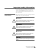
Important safety information For your safety and protection, read this entire manual before you attempt to install the DW4020. In particular, read this safety section carefully. Keep this safety information where you can refer to it if necessary. Types of warnings used in this manual This section introduces the various types of warnings used in this manual to alert you to possible safety hazards.
x • Important safety information 1031484-0001 Revision 2
About this document Scope and audience This manual describes installing and servicing the DIRECWAY® DW4020 terminal. It addresses installers, network system engineers, and network operators who install, commission, operate, and maintain the system. Audience profile The DW4020 is installed by professional telecommunications installers. This product cannot be installed by the end user. There are four primary audiences: • HNS Installers – at this time, only HNS installers will install this product.
Conventions This manual follows the typographical conventions shown below to help clarify instructions: Example Click Exit. Indicates the names of command buttons that execute an action. The system displays the following: Are you ready? Indicates all system messages and prompts as the system displays them. Type exit Indicates operator input. Enter a value in the Time field. Indicates the names of fields on windows.
Chapter 1 Introduction This chapter addresses the following topics: • DW4020 purpose and components on page 1 • Characteristics and identification of equipment on page 2 DW4020 purpose and components The DW4020 is designed to provide multiple computer connections through a single DIRECWAY® terminal.
These units, in combination with an antenna, provide satellite connectivity for multiple local area network (LAN) hosts through one DIRECWAY System. All the necessary software resides on the Gateway, which serves as the router. Because the software is on the Gateway, there is no need for a computer to run client software, unlike previous versions of DIRECWAY. Figure 1 illustrates the functionality of the DW4020 within a DIRECWAY network. Note that the DW4020 is independent of operating platforms.
. Table 1: DW4020 hardware characteristics Characteristic DW4020 Main processor 200Mhz Ethernet 10/100 4 ports (switched) RJ-45 Main Memory 32MB Flash Memory 8MB Serial Port Asynchronous RS232 USB Port One USB 1.1 (Type A) Table 2: DW4020 physical characteristics Characteristic Value Physical Dimensions Height Width Depth Weight 5.75 inches 6.5 inches 8.8 inches 4.0 lbs.
Table 3: Cable requirements Grounding and Cable Choice Your choice of grounding scheme may affect your choice of cable. Note that meeting the National Electrical Code grounding requirements is easier if you use RG-6 with quad shield. However, you can also use standard RG-6 and ground according to the Code or the instructions in the antenna installation manual.
Chapter 2 Installing the indoor equipment System pre-installation Together, the receive modem, the transmit modem, and the Gateway are called the DW4020 and sometimes referred to as the indoor unit (IDU). The receive modem is also called the IRU; the transmit modem is also called the ITU; and the Gateway is sometimes called the GWH. The three units must be stacked correctly to ensure proper heat dissipation.
Two DW4020 installation There two ways to install the DW4020. methods • If an analog phone line is available, assemble and install the system using the instructions in Installing the system using a modem on page 11. This method is preferred and is usually the one that will be used. • If no analog phone line is available, you must configure the DW4020 through the serial port. Follow the instructions in Appendix C. Summary of DW4020 DW4020 installation is a 10-step process. installation process 1.
CAUTION A password from the authorized installer is required before the National Operations Center will activate the system. CAUTION Professional installation and service of the antenna assembly is required by the Federal Communications Commission because the radio transmits radio frequency energy. • The two-way antenna assembly must be installed in a location or manner not readily accessible to children. • The two-way antenna assembly must be installed at least 5 feet (1.
Installing DIRECWAY installation software on installer laptop The installation software for the DW4020 is on a CD. The software will enable you to register DW4020 customers. You need a receive modem (IRU) to install the software on your installer laptop PC. Do not confuse the installation software with the software that is downloaded to the Gateway via satellite during registration. The DW4020 installation software enables you to register customers and configure the DW4020 for operation.
Installing the software Do not connect USB cable to the receive modem until prompted. You may use the cable that came with the unit, or a different cable if you need a longer one. 1. Load the installer software CD into your laptop computer. The installation wizard should appear. If it does not, select Start→Run, browse to the CD drive, select it, and select setup.exe. Figure 3: Installation screen 2. Select Install Software. A Setup screen appears. 3. Select Next. An Agreement screen appears. 4.
Figure 4: Device Installation Status Figure 5: Websetup Welcome screen 10 Chapter 2 • Installing the indoor equipment 1031484-0001 Revision 2
Installing the system using a modem You need all the items shown in Figure 6. Some of them are in the modem installation kit or inside the antenna box. If you are using Web commissioning, you must provide an Ethernet cable to connect between the DW4020 and installer PC. If Web commissioning is not available, you must provide a 9-pin female/female (F/F) null modem serial cable. The serial cable can be used to configure the DW4020 via the serial port. Appendix C – Installing the DW4020 Manually, on page 77.
The power supply The DW4020 uses a power supply with the part number P/N: 1031105-0001. The part number is on a sticker on the power supply. Verify that you are using the correct power supply. Do not use anything but the power supply supplied with the DW4020 system (1031105-0001). Be sure the power supply is labeled ADP 64AB B in the upper right hand corner of the label, above the bar codes. See Figure 7. CAUTION • This unit’s performance may suffer if the wrong power supply is used.
Assembling the Follow the steps below and refer to the illustrations on page 13 components, modem through page 16 to assemble the DW4020 components. Note that installation method some cables are connected to the installer laptop until commissioning is complete. Then the DW4020 is connected to the customer’s computer. Before beginning the installation, be sure that you have installed the installation software correctly. See Installing the software on page 9.
Figure 8: Mount the components on two clips Figure 9: Attach the other clips 14 Chapter 2 • Installing the indoor equipment 1031484-0001 Revision 2
Receive modem Transmit modem Gateway Figure 10: Component stack Chapter 2 • Installing the indoor equipment 1031484-0001 Revision 2 15
5. Connect the component interconnection cables. See Figure 11. A USB cable connects the receive modem and the installer PC; you may use a longer cable rather than the one that is supplied if you wish. An Ethernet cable connects the Gateway and the installer PC. A 25-pin connector cable connects the transmit and receive modems. A power supply adapter cable provides power to the Gateway and receive modem. See Figure 11.
Installer laptop PC Ethernet port AC power cord Ethernet cable USB cable Receive modem Transmit modem Power supply Gateway DC power cord Figure 12: Connect power cord Connect Ethernet, power up, and read the Gateway LED display After you assemble the DW4020, connect it to the installer laptop with Ethernet cable. Plug it into a 110 V wall outlet, power strip, or surge protector. The Gateway LED display will cycle.
The transmit and receive modems have their own LEDs, which show their status. These are described in The modems’ LEDs on page 18. For more information on LEDs, troubleshooting, and LED blinking and status codes, see Chapter 4 – DW4020 LEDs and troubleshooting, on page 53. Note that normal Gateway operation alone doesn't imply normal DW4020 operation.
TX LED. The LEDs’ status indicate various conditions. Table 5 describes the basic states. The LEDs may also indicate various conditions through blink patterns. The numbers in brackets are the status codes discussed in The System Status indicator on page 36. If the modem does not appear to be functioning, check all cable connections. If they are secure, cycle the power by unplugging the power cord at the power supply and plugging it back in.
Ethernet port LEDs Each of the four Ethernet ports on the DW4020 has two LEDs associated with it. One LED is green and one is yellow. See Figure 13. The green LED will be on if power is applied to the DW4020 and a 100baseT Ethernet device is connected to the corresponding Ethernet port. Otherwise, the green LED will be off. If the power is on and the light is off while a network device is connected, then the device is a 10baseT device and the port is autosensing.
Running the DW4020 installation software, commissioning, and registering the customer The DW4020 installer’s computer software is basically DIRECWAY 4.0 software with some functions, such as interacting with a browser, removed. It is used to run Websetup and commission the customer. There are three registration servers, one each for consumer, small office/home office, and enterprise. Before you select the registration server, check the work order and confirm which service option the customer has chosen.
4. Websetup will first detect the Gateway and the modem. See Figure 15. 5. Then Websetup will check for an existing connection to WebACS. Websetup may bring up a dial-up connection if necessary. See Figure 16.
Figure 17: Registration Connection - Authentication 6. Websetup will then authenticate the receive modem serial number and enable it. See Figure 17. 7. Websetup then presents a series of forms to the user to complete registration. See Figure 18 through Figure 20. The appearance of the forms may vary, and the forms’ content may change from time to time. For example, a SOHO customer Service Offerings screen shown in Figure 19will be different from a consumer screen.
Figure 19: Service Offerings Figure 20: Registration Note: The registration information in Figure 20 is very important. Make certain this information is recorded on the cover of the customer’s User Guide. That way the customer will have important information available should their DW4020 not function and they need to call technical support.
8. After the customer enters registration information, write the information in Figure 20 on the cover of their User Guide. 9. Select Continue in the Registration screen in Figure 20. The Antenna Pointing - Antenna Location screen appears. See Figure 21. Figure 21: Enter ZIP code 10. Verify that the ZIP code shown matches the ZIP code for the installation site. If not, correct it. Select Next. The Antenna Pointing - Receiver screen appears. See Figure 22.
Figure 22: Antenna Pointing - Receiver Figure 23: Finish Figure 24: 26 Chapter 2 • Installing the indoor equipment 1031484-0001 Revision 2
Post-commissioning Peak the satellite signal In post-commissioning, you peak the satellite signal, attach the DW4020 to the customer computer that has a functioning Ethernet interface, and confirm the customer can surf the Internet. 1. Unplug the DW4020 power cord from the wall outlet or surge protector. 2. Remove the phone line and network cable from the installer laptop PC. 3. Remove the network cable from the Gateway and unplug the USB cable from the receive modem. 4.
Figure 26: Antenna Pointing - Receiver 9. Use the Elevation, Azimuth and Polarization values to adjust the antenna to achieve maximum receive signal strength. 10. Select the ACP (auto cross-pol) checkbox. If it is not available, wait five minutes; the system will update. 11. Select Next to go to the Antenna Pointing - Transmitter screen. See Figure 27.
12. Select the Manual fine pointing mode radio button. 13. Select Start Test. Adjust the antenna to achieve maximum transmit isolation. 14. When the unit consistently passes the manual transmit test, bolt the antenna securely before going to Step 15. 15. After the antenna is bolted, select Stop Test. See Figure 28. 16. Then select the Automatic radio button and select Start Test to start the automatic ACP test. See Figure 29. 17. Make sure the test passes. 18. Select Exit after passing the test.
Figure 30: ACP passes; select Exit Connect to customer computer and confirm surfing 30 1. Disconnect the USB cable from the installer’s PC. 2. Connect the receive modem to the Gateway using the USB cable supplied with the unit. See Figure 31.The DW4020 will re-initialize and come back up in normal mode. 3. Connect the receive coaxial cable to the receive modem and the transmit coaxial cable to the transmit modem. See Figure 31. 4. Plug the power cord into the wall outlet or surge protector. 5.
If the customer cannot surf If the customer cannot surf, configure your installer laptop so its network properties match the customer’s. Refer to Appendix D for exact instructions for setting your network properties. Then: Ethernet 1. Start a Web browser on the installer laptop. 2. Enter the Gateway IP address in the browser URL location bar and press Enter. If the DW4020 is functioning, the User Interface appears. 3. Enter an URL for a known Web site, such as abc.com or cnn.com.
32 Chapter 2 • Installing the indoor equipment 1031484-0001 Revision 2
Chapter 3 The User Interface In the Version 1.0 software, DW4020 status information was available on menus accessed through the serial port via Hyperterminal. In the Version 2.0 software, a browser-based User Interface provides information about system status, system configuration, online documentation, and firewall configuration. Access it if the DW4020 doesn’t seem to be functioning properly, to find system information for configuring networks, or to check system performance.
How to access the User Interface The User Interface is accessed through any browser, such as Internet Explorer or Netscape. Follow the steps below to set up an entry for the User Interface in a browser. The steps are written for Internet Explorer or Netscape, but you can use a similar procedure for any browser. 1. Go to Start→Programs→Internet Explorer (or Netscape). The browser interface appears. 2. Place the cursor in the Internet Explorer Address bar or the Netscape Location Bar. 3.
The Home screen The Home screen has system indicators across the top. There are menu items in a column along the left. The system indicators consist of the following: • System Status reports the strength of the receive signal, the status of the receive and transmit modems, and software download status. If System Status is colored green, the DW4020 is functioning properly. If there is a problem, it is colored red and the word “PROBLEM” appears below System Status. See Figure 33.
The System Status indicator Clicking on System Status will display a System Status screen. See Figure 34. Figure 34: System Status screen The screen consists of the following fields. • Signal Strength - indicates the signal quality factor (SQF), which is the strength of the receive signal. If SQF is 30 or below, the antenna must be repointed by a certified professional installer. • Transmit Status - indicates the status of the transmit modem. • Receive Status - indicates the status of the receive modem.
If there is a problem with any of these four status elements, a red exclamation mark will appear in the status field. In addition, if there is a problem with the Transmit Status or Receive Status, an error message and an error code will appear in blue. You can click on the error message and an explanation of the error condition and what action might solve it will appear. See Figure 35. The tables below provide a more detailed explanation of status codes, error messages, and corrective actions.
If corrective measures do not solve a problem, contact technical support. TxCode 8 means the transmit modem is working properly. It is the code you will see most of the time. Note: Remember that IRU refers to the receive modem, and that ITU refers to the transmit modem.
Table 6: Transmit status (TxCode) messages and corrective actions 5 The transmitter is not locked to the network timing No action is necessary if this condition occurs from time to time and quickly resolves itself. If this issue persists, it is likely due to a NOC-related service issue. The condition may also be due to Indoor Transmit Unit failure; in rare cases, the Transmit unit may fail and may have to be replaced.
Table 6: Transmit status (TxCode) messages and corrective actions 14 The transmitter is not available because ranging has failed This condition indicates that the transmitter is not operational because ranging has failed. Ranging is the process that adjusts the satellite transmitter timing and power. The satellite transmitter conducts ranging as needed to ensure that it can communicate successfully with the Network Operations Center.
Table 6: Transmit status (TxCode) messages and corrective actions The transmitter is disabled because a transmit pointing test failed This condition occurs when the transmitter fails a transmit pointing test. This indicates that the transmitter did not meet the minimum specifications required. This is likely due to an antenna installation problem. The antenna installer needs to fine-point the antenna. The transmitter will not transmit until the transmit pointing test passes.
CAUTION Never unplug the power cord from the DW4020 while it is powered on. Always disconnect the power cord from the power supply, wall outlet, or surge protector. Receive Status messages The following messages may appear in the Receive Status field. The Comments section gives more information about each code, and describes any possible corrective measures. See Figure 36 on page 41 for corrective measure involving cables or the power supply.
Table 7: Receive code (RxCode) messages and corrective actions 3 The receiver is not locked to a signal If the DW4020 had been operating previously, this status is probably due to inclement weather conditions and will be corrected when the weather improves. This condition can also indicate that the IRU is unable to receive the signal from the NOC. This is also associated with a signal level less than 30.
• Frames Received - displays the number of frames the receive modem has received. • Frames with Errors- displays the percentage of bad frames received. • Bad Key Frames - packets received over satellite that could not be decrypted successfully. A non-zero value indicates commissioning problems. (Clicking on the field will display this definition in the Web interface.
• Number of Failed Transmissions- number of times the ITU failed to transmit data. • Number of Packets Submitted for Transmission- number of packets submitted to the transmit modem. Figure 38: Transmit Statistics screen System Information The System Information screen displays a number of fields. While all the information may be useful at some time, the most important is discussed below. Note: Print the System Information screen and give it to the customer.
– Longitude - displays the satellite’s longitude. – Receive Polarization - polarization orientation. • Software Configuration section- WEB Acceleration, NAT, and DHCP are enabled or disabled as per a customer’s service offering and cannot be changed by the customer. – Web Acceleration - Allows fast access to Internet Web sites and high-speed data download from the Internet. – Network Address Translation (NAT) - typically used to allow multiple computers to share a single address on the Internet.
The Connectivity Test Menu You may lose connectivity to a particular server due to the Internet and/or the satellite network being heavily loaded or due to the server being down. If possible, check connectivity to some other server on the Internet to ensure it is not a server specific problem. Follow the procedure below for troubleshooting: Network Operations Center Use the Connectivity Test from the left pane to check (NOC) Connectivity connectivity to the DIRECWAY NOC.
Figure 40: Connectivity Test Internet Connectivity Try pinging the DIRECWAY Internet server (www.direcway.com). Note: If you are an enterprise customer and your enterprise has a backbone connection to the Network Operations Center, the DIRECWAY Internet server may not be accessible. In such a case, you should try to ping your enterprise's Internet server.
The Firewall Menu The User Interface enables customers to enable a firewall and configure its rules. If they use the firewall, they must configure it properly for maximum protection. They should be aware that even an optimally configured firewall cannot be guaranteed to keep out all potentially harmful traffic. A discussion of the principles applied when setting up a firewall is in the DW4020 User Guide (HNS 1032564-0001).
Figure 41: Firewall Settings 50 Chapter 3 • The User Interface 1031484-0001 Revision 2
Table 8: Port numbers and protocols The Help Menu Port Number Internet Application or Protocol 7 Echo 21 FTP control port 23 Telnet 25 Simple Mail Transfer Protocol (SMTP) 53 Domain Name Server (DNS) 70 Gopher 79 Finger 80 Hyper Text Transfer Protocol (HTTP) 107 Remote Telnet Service (RTELNET) 110 Post Office Protocol - Version 3 (POP3) 119 Network News Transfer Protocol (NNTP) 6667 Internet Relay Chat (IRC) The Help Menu contains information about receive and transmit modem stat
myDIRECWAY Customers can click on myDIRECWAY to go to myDIRECWAY.com. Members get access to a variety of interactive tools and can check usage online, test satellite speed, manage passwords, and more. myDirecway.com is not an installer resource. Software updates and the User Interface 52 Chapter 3 • The User Interface 1031484-0001 Revision 2 The DW4020 software will be updated periodically to provide access to new features and for performance enhancements.
Chapter 4 DW4020 LEDs and troubleshooting The DW4020 LEDs can provide information for troubleshooting units that aren’t functioning at all, or don’t seem to be functioning as well as they might. The LEDs can show modem or Gateway operational status--whether they are connected, powered up, or working at al. The LEDs can also blink in patterns that correspond to the TxCode and RxCode discussed in The System Status indicator on page 36. Finally, the Gateway Ethernet ports have LEDs that indicate their status.
DW4020 LEDs status This section describes the LEDs’ appearance during typical DW4020 operation. It also describes their appearance when some basic problem is occurring. Normal operation, no When the DW4020 is powered on but not receiving or transmit or receive transmitting data, it appears as shown in Figure 43. The modems’ READY LEDs are continuously lit. Both the Gateway LEDs are continuously lit.
Normal operation, data During normal DW4020 operation, the modems’ READY LEDs being sent and received are continuously lit, the RX and TX LEDs blink as they pass data, and both the Gateway LEDs are continuously lit, as shown in Figure 44.
Receive modem READY LED not lit. Note that in many cases other modem LEDs will not be lit either.
Transmit modem READY If the transmit modem is not operating normally and its READY LED not lit LED is not lit, as shown in Figure 47, take the following steps. • Check that the receive modem READY LED is continuously lit. If not, try the sequence in Problem: receive modem READY LED not on on page 55. • Check that the 25-pin connector is attached securely. See Figure 46. • Check to make sure the power cord is securely attached to the receive modem and plugged into the wall outlet or surge protector.
Gateway LEDs not lit If the Gateway does not seem to be functioning and its LEDs are not lit, and the receive modem READY LED blinks as shown in Figure 48, take the following steps. • Check to make sure the power cord is securely attached to the Gateway and receive modem and plugged into the wall outlet or surge protector. See Figure 46. If the power cord was loose, the Gateway and receive modem READY LEDs will come on when power is restored.
Gateway LEDs flash, receive If the Gateway does not seem to be functioning and its STATUS modem READY LED off or LED flashes amber, and the receive modem READY LED blinks flashing or is not lit, as shown in Figure 48, take the following steps. • Check to make sure the USB cable is securely attached to the Gateway and receive modem. See Figure 46. If the cable was loose, the Gateway and receive modem READY LEDs will come on when it is reattached.
LED blinking indicating The DW4020 modems’ READY LEDs can blink in various status codes patterns. These patterns correlate to the status codes discussed in Transmit Status messages on page 37 and Receive Status messages on page 42. If you can see the patterns, you also have access to the User Interface. It will be easier to find out what the status of the DW4020 is via the interface than the LED status blinking. The blink patterns are described below for your information.
Receive READY LED Pattern Corresponding receive status message Fast Alternating Prior to downloading software– This is a continuous fast-blinking pattern, with the RX LED being the inverse of the Ready LED. No corresponding message.
Ethernet port LEDs Each of the four Ethernet ports on the DW4020 has two LEDs associated with it. One LED is green and one is yellow. See Figure 50). The green LED will be on if power is applied to the DW4020 and a 100baseT Ethernet device is connected to the corresponding Ethernet port. Otherwise, the green LED will be off. If the power is on and the light is off while a network device is connected, then the device is a 10baseT device and the port is autosensing.
Glossary D H Dotted decimal notation - An IP address consists of 32 bits. Rather than working with 32 bits at a time, it is a common practice to segment the 32 bits of an IP address into four 8-bit fields called octets. Each octet is converted to a decimal number (the Base 10 numbering system) in the range 0-255 and separated by a period (a dot).
IP address - a 32-bit number that identifies each sender or receiver of information that is sent in packets across the Internet. An IP address has two parts: the identifier of a particular network on the Internet and an identifier of the particular device (which can be a server or a workstation) within that network. On the Internet itself - that is, between the router that move packets from one point to another along the route - only the network part of the address is looked at.
Turbo Internet - A high-speed satellite link from the Internet, allowing users to download information at a very high rate. Turbo Internet services provide asymmetric connections between a customer PC and the Internet. This enables users to download very large files at a very high rate of speed.
66 • Glossary 1031484-0001 Revision 2
Abbreviations and Acronyms Abbreviation or Acronym Term DHCP dynamic host configuration protocol GWH Gateway host IANA Internet Assigned Numbers Authority IP Internet protocol IRU indoor receive unit ISP Internet service provider ITU indoor transmit unit LAN local area network NAT network address translation NMC network management center NOC network operations center OPI outdoor pointing interface PEP performance enhancing proxy RX receive SDL software download TCP transmiss
68 • Abbreviations and Acronyms 1031484-0001 Revision 2
Appendix A Lat/Long Decimals to Minutes Table Use the following procedure to determine your latitude and longitude decimal to minutes conversion. 1. Enter the whole number part of the site's longitude into the VSAT Longitude in degrees field in the Configure Boot Parameters screen. 2. Take the two digits immediately to the right of the longitude decimal point (without doing any rounding) and use the chart below to translate these two digits into the number of minutes. 3.
Right of Decimal .01 .02 .03 .04 .05 .06 .07 .08 .09 .10 .11 .12 .13 .14 .15 .16 .17 .18 .19 .20 .21 .22 .23 .24 .25 .26 .27 .28 .29 .30 .31 .32 .33 .34 .35 70 Minutes 1 1 2 2 3 4 4 5 5 6 7 7 8 8 9 10 10 11 11 12 13 13 14 14 15 16 16 17 17 18 19 19 20 20 21 Right of Decimal .36 .37 .38 .39 .40 .41 .42 .43 .44 .45 .46 .47 .48 .49 .50 .51 .52 .53 .54 .55 .56 .57 .58 .59 .60 .61 .62 .63 .64 .65 .66 .67 .68 .69 .
Appendix B The Internet and the DW4020 Internet protocol (IP) and transmission control protocol (TCP) The Internet Protocol (IP) provides a format for moving packet data from node to node. The IP enables data to move from department to organization, to a region, across regions, to destination organizations, and to departments. The IP layer serves as the basis for other protocol layers, as shown in Table 10. The transmission control protocol (TCP) verifies correct delivery of data.
their TCP limits, vastly increasing the overall throughput. This technique is also known as TCP spoofing. IP addressing and the IP provides a method of constructing a network of networks DW4020 where computers and networks made by different manufacturers and conforming to different standards can exchange information. The IP is layered on top of vendor-specific protocols. The data to be sent is divided into packets.
card.” The business owner can then assign his individual computer connections the numbers as shown in Figure 51. Internet address 192.77.43.2 192.77.43.4 192.77.43.3 192.77.43.5 Figure 51: IP addresses assigned to individual computer connections A large organization like a university might apply for a class B network, in which the first two bytes are assigned and the last two bytes are available to the university to assign up to 64 thousand computers in sub-network LANs.
Private IP addresses As Internet use has increased, more and more IP addresses have been assigned. There is not an infinite number of IP addresses, and IANA is concerned that the supply of unique IP addresses could be exhausted. One way to conserve IP addresses is to assign them only to hosts that are designated as "public." Hosts that are designated as "private" do not need unique IP addresses.
10.0.0.0 - 10.255.255.255 (10/8 prefix) 172.16.0.0 - 172.31.255.255 (172.16/12 prefix) 192.168.0.0 - 192.168.255.255 (192.168/16 prefix) The first block is the "24-bit block," the second is the "20-bit block," and to the third is "16-bit" block. Note that the first block is nothing but a single class A network number, while the second block is a set of 16 contiguous class B network numbers, and third block is a set of 256 contiguous class C network numbers.
DW4020s provide connections The DW4020 provides connectivity from a satellite network to multiple computers. From the point of view of the individual computer user, the DW4020 provides the link to the outside world. DW4020s direct data traffic by inspecting the IP addresses. A DW4020 is assigned two IP addresses, one in each network that it links. Figure 52 illustrates a typical connection scheme for the DW4020. IRU 25 Pin Connector ITU GWH LAN IP Address: USB From LAN 170.15.100.
Appendix C Installing the DW4020 Manually The installation specification may direct you to install the DW4020 using the serial port. You would connect the installer laptop to the Gateway via the serial ports with a 9-pin female to female (F/F) null modem serial cable. That cable is not included with any DW4020 equipment. Items needed for installation You need all the items shown in Figure 53. Some of them are in the modem installation kit or inside the antenna box.
The power supply DW4020 users must use a power supply with the part number P/N: 1031105-0001. The part number is on a sticker on the power supply. Verify that you are using the correct power supply. Do not use anything but the power supply supplied with the DW4020 system (1031105-0001). Be sure the power supply is labeled ADP 64AB B in the upper right hand corner of the label, above the bar codes. See Figure 54. CAUTION • This unit’s performance may suffer if the wrong power supply is used.
Assembling the Follow the steps below and refer to the illustrations on page 80 components through page 83 to assemble the DW4020 components. After you assemble the components, you can plug in the power supply and observe the LED display cycling, as explained in The DW4020 LEDs on page 86. CAUTION • The components must be stacked in this order: Gateway on bottom; transmit modem on top of Gateway; receive modem on top of transmit modem. See Figure 57.
Figure 55: Mount the components on two clips Figure 56: Attach the other clips 80 Appendix C • Installing the DW4020 Manually 1031484-0001 Revision 2
Receive modem Transmit modem Gateway Figure 57: Component stack Appendix C • Installing the DW4020 Manually 1031484-0001 Revision 2 81
Ethernet card 6. Connect the component interconnection cables. A short USB cable connects the receive modem and the Gateway. A 25-pin connector cable connects the transmit and receive modems. A power supply adapter cable provides power to the Gateway and receive modem (see Figure 58). 7. Connect the receive coaxial cable to the receive modem and the transmit coaxial cable to the transmit modem (see Figure 59).
Ethernet card 8. Connect up to four Ethernet cables to the network ports on the Gateway (see Figure 60). Either a straight-through or a cross-over Ethernet cable can be used. The four ports labeled 1 through 4 are Ethernet 10 Base - T/100 network ports. They enable you to connect to other computers via an Ethernet connection. (Reference UL 60950, Annex NAA, Subclause reference 6, page 322.
Ethernet card AC power cord Receive modem Transmit modem Power supply DC power cord Gateway Ethernet cables T0091013 Figure 61: Connect power cord Figure 62: Final assembly 84 Appendix C • Installing the DW4020 Manually 1031484-0001 Revision 2
Powering up and reading After you have assembled the DW4020, plug it into a 110 V wall the DW4020 LED display outlet, power strip, or surge protector. The Gateway LED display will cycle as shown in Table 12. The cycling completes in less than a minute. Note: In countries outside North America, the DW4020 may be plugged, with a physical adapter, directly into a 220 V outlet. Different countries may have different standards and requirements.
The DW4020 LEDs The receive and transmit modems have LEDs on their front panels. Both modems have a green READY LED. The receive modem has a green RX LED. The transmit modem has a green TX LED. The LEDs’ status indicate various conditions. Table 13 describes the basic states. The LEDs may also indicate various conditions through blink patterns. Tables 7 and 8 explain these. The numbers in brackets are the status codes discussed in The System Status indicator on page 36.
• Check if the LEDs on the back of the Gateway or on or off. The LAN ports on the back of the Gateway have LEDs. See Ethernet port LEDs on page 94. • Contact Customer Care. If the corrective actions described in this chapter and Chapter 3 – The User Interface do not solve the problem, contact technical support. The DW4020 LEDs The receive modem has a RX and a READY LED. The transmit modem has a TX and a READY LED. The Gateway has a STATUS and READY LED.
Normal operation, data During normal DW4020 operation, the modems’ READY LEDs being sent and received are continuously lit, the RX and TX LEDs blink as they pass data, and both the Gateway LEDs are continuously lit, as shown in Figure 64.
Receive modem READY LED not lit. Note that in many cases other modem LEDs will not be lit either.
Transmit modem READY If the transmit modem is not operating normally and its READY LED not lit LED is not lit, as shown in Figure 67, take the following steps. • Check that the receive modem READY LED is continuously lit. If not, try the sequence in Problem: receive modem READY LED not on on page 88. • Check that the 25-pin connector is attached securely. See Figure 66. • Check to make sure the power cord is securely attached to the receive modem and plugged into the wall outlet or surge protector.
Gateway LEDs not lit If the Gateway does not seem to be functioning and its LEDs are not lit, and the receive modem READY LED blinks as shown in Figure 68, take the following steps. • Check to make sure the power cord is securely attached to the Gateway and receive modem and plugged into the wall outlet or surge protector. See Figure 66. If the power cord was loose, the Gateway and receive modem READY LEDs will come on when power is restored.
Gateway LEDs flash, receive If the Gateway does not seem to be functioning and its STATUS modem READY LED off or LED flashes amber, and the receive modem READY LED blinks flashing or is not lit, as shown in Figure 68, take the following steps. • Check to make sure the USB cable is securely attached to the Gateway and receive modem. See Figure 66. If the cable was loose, the Gateway and receive modem READY LEDs will come on when it is reattached.
blinking. The blink patterns are described below for your information.
Ethernet port LEDs Each of the four Ethernet ports on the DW4020 has two LEDs associated with it. One LED is green and one is yellow. See Figure 70. The green LED will be on if power is applied to the DW4020 and a 100baseT Ethernet device is connected to the corresponding Ethernet port. Otherwise, the green LED will be off. if the power is on and the light is off while a network device is connected, then the device is a 10baseT device and the port is autosensing.
Communicating with the Gateway through the serial port Connecting the Gateway and laptop After the Gateway finishes the LED sequence, you will use a laptop PC to communicate with the Gateway via a serial cable. (You can also use a desktop PC.) You access the Boot Parameters screen and set the parameters. You also point and cross-pol the antenna. In order to complete the parameters, you will need your installer ID and the information shown in Figure 80 on page 102. 1.
a. Select Start→Accessories→Hyperterminal and click on the Hyperterminal file (see Figure 72). The Connection Description window appears (see Figure 73). The red and yellow phones icon is highlighted in blue. You will establish a new connection.
b. Enter DW4020 in the New field. c. Select OK. The Connect To window appears. d. Select COM1 from the Connect Using pull-down list (see Figure 74). (Select COM2 is you want to use that port.) Figure 74: Connect To window e. Select OK. The COM1 Parameters window appears. f. Configure the Port Settings by selecting the parameters below from the appropriate pull-down list (see Figure 75).
Figure 75: COM1 Properties window and pull-down menus g. Select OK. The window disappears. h. Select File→Save As. The Save As window appears. i. Enter DW4020 in the File name field and select Save. The window disappears. Now you will simply be able to select the DW4020.ht file when connecting the Gateway and the laptop during future installs. j. Select Call→Connect. The laptop will connect to the Gateway.
4. Press ENTER at the Hyperterminal prompt to display the initial Install Console screen shown in Figure 76. Figure 76: Initial Install Console screen Note: For all future Gateway installations, use the DW4020.ht file you saved to connect the Gateway and laptop. Start Hyperterminal. Select File→Open→DW4020.ht. The Gateway and laptop will connect. 5. Press ENTER to display the Main Menu shown in Figure 77.
6. Enter c to display the Satellite Interface Statistics menu (see Figure 78). Figure 78: Satellite Interface Statistics menu with Display Satellite Interface Serial Number displayed 7. Enter c to display the satellite interface serial number (see Figure 78). If the electronic serial number is different from the barcode receive modem serial number, call the installer hotline for the DW4020 series and request the serial number be corrected.
Configuring Boot Use Configure Boot Parameters to configure the Gateway for Parameters outroute reception and downloading of software. For initial installation, most parameters must be entered, except for VSAT Return Path, which is always “Inroute.” Thus, you will need your installer ID, and you will need all necessary information to enter data for the fields marked with an asterisk in Figure 80.
Creation Date: Feb 8 2002, 11:43:08 Current Gateway Image Executing: Main.
3. When you have entered all parameters, return to the Main Menu and enter pw. This saves the configuration parameters to the flash memory. At this point, depending on the parameters that were modified, the Gateway may reset. 4. A message Writing the configuration -are you sure (y/n) appears. Enter y. At this point, depending on the parameters that were modified, the Gateway should reset. If it does not reset, enter rr to do a Gateway reset. 5.
CAUTION • The two-way satellite dish assembly emits radio frequency energy when in the transmit mode. • Unplug indoor power connection before performing maintenance or adding upgrades to any satellite dish components. • To avoid risk of injury, do not place head or other body parts between feed horn and reflector when system is operational.
2. At the Installation Menu prompt, enter a to obtain antenna pointing values and assigned satellite parameters. The Antenna Pointing - Receiver screen in Figure 82 appears. Figure 82: Antenna Pointing - Receiver The SQF represents the strength of the received signal relative to noise. SQF is an integer value between 0 and 99. The SQF value is interpreted as follows: – 0-29. The receive modem is not locked onto the desired signal. The value increases as the Gateway receives stronger signal power. – 31-99.
Antenna Pointing - Transmitter, The manual cross-polarization function can be used to adjust the Manual antenna and peak the antenna’s transmit polarization for maximum isolation. You can also use manual pointing to adjust polarization after failing the automatic cross-polarization test. 1. Enter C at the Installation Menu prompt. The Antenna Pointing - Transmitter, Manual screen appears. Otherwise, the screen shows the current queue position until the test can be run.
CAUTION Any time you enter the DW4020 Installation Menu, the transmitter is turned off for safety reasons. Do not enter "I" to access the Installation Menu after this point unless instructed to do so by a technician at the NOC. Figure 83: Display Main Statistics Range value Ranging may have to be initiated by the NOC to adjust for differences in delay due to distance to the satellite. Check your installation specification to see if this is necessary.
Verifying software download If the Gateway is configured correctly for outroute reception and SQF is greater than 30, it will acquire the outroute. As soon as the Gateway acquires the outroute, it begins to look for the Hub Server in the data stream to perform software download. 1. To monitor software download (SDL) progress, enter f at the Main Menu prompt to select Software Download Monitor. 2. The following message is displayed at the bottom of the screen: SDL Initialization complete.
6. On successful download, the Gateway automatically resets to reflect the new software. The new configuration takes effect. Figure 84: Gateway reset 7. At the Main Menu prompt, select f to monitor SDL progress. The following messages are displayed: SDL Initialization complete. Awaiting first heartbeat msg. Received first heartbeat message. All files downloaded. No pending changes. The DW4020 may now be hooked up to either a configured PC or network.
DW4020 status information via the serial port The DW4020 has no serviceable parts. However, you may be able to debug units with help from the network operations center (NOC). You access the menus below via the serial port, just as when you set up the DW4020. Verifying correct DW4020 operation You can verify that the DW4020 unit is receiving and processing data by following the steps given below. 1. Enter A at the Main Menu to access Satellite Interface Statistics. 2.
Displaying traffic statistics At the Satellite Interface Statistics submenu enter B to select Display Traffic Statistics. The screen in Figure 86 appears.
The Final Test Menu The Final Test Menu is not used by installers. It is used at the factory to ensure the various DW4020 components are functional. The menu is shown below. Final (a) (b) (c) (d) (g) (z) Test Menu: LED Test Pattern Ethernet Ports Test Modem Signal Test USB Port Test Factory Information Read Return to Main Menu Figure 88: Final Test Menu Other options This section describes some other options in the Main Menu.
Appendix D Configuring the installer laptop for IP addressing This chapter explains how to configure your installer laptop PC so that you can register the DW4020. All DW4020s come from the factory with Dynamic Host Configuration Protocol (DHCP) enabled. Therefore, your installer laptop PC must have DHCP enabled and set to automatically obtain IP addresses.. Windows 98SE and ME 1. On the client computer, go to Start→Settings→Control Panel and double-click Network. See Figure 91.
Figure 92: Network window 3. Select the TCP/IP entry associated with Network Interface Card (NIC) and then select Properties. The TCP/IP Properties window appears. See Figure 93. 4. In the IP Address tab, select Obtain an IP address automatically. 5. Select the Gateway tab. Remove any installed gateways by selecting them and selecting Remove. See Figure 94. 6. Select the Disable DNS radio button on the DNS Configuration tab. 7.
8. Select OK to close the list of network components. Windows may request the installation CD-ROM to complete updating the TCP/IP settings. 9. Restart the computer if it does not do so automatically. Figure 93: TCP/IP Properties Figure 94: Gateway tab Appendix D • Configuring the installer laptop for IP addressing 1031484-0001 Revision 2.
Windows 2000 1. On the client computer, go to Start→Settings→Control Panel and double-click Network and Dial-up Connections. 2. A list of network adapters appears. See Figure 95. The Local Area Connection adapter must be listed. If it is not, the network is not installed correctly. 3. Right-click the Local Area Connection icon that represents the network adapter that connects the computer to the DW4020 and select Properties. The Local Area Connections Properties window appears. See Figure 96. 4.
5. Select Internet Protocol (TCP/IP). Be careful not to uncheck the checkbox. 6. Select the Properties button. The Internet Protocol Properties window appears. See Figure 97. 7. Ensure that both Obtain an IP Address Automatically and Obtain DNS Server Address Automatically are selected. If not, select them. 8. Select OK to close the open dialog boxes and finish the configuration. 9. Restart the computer even if Windows does not require you to do so.
Windows XP 1. Go to Start→Settings→Control Panel. Double-click the Network and Dial-up Connections icon. Note: If the Control Panel is in category view select Network and Internet Connections then select Network Connections. 2. A list of network adapters will be displayed. A Local Area Connection must be listed under LAN or High-Speed Internet. If not, the network is not installed correctly. See Figure 98. 3.
Figure 99: Local Area Connection Properties Figure 100: Internet Protocol Properties Appendix D • Configuring the installer laptop for IP addressing 1031484-0001 Revision 2.
120 Appendix D • Configuring the installer laptop for IP addressing 1031484-0001 Revision 2.
Appendix E Installation checklist Installation summary and checklist The following DW4020 components are installed: • Antennas (outdoor unit or ODU) • Coaxial cable (IFL) • DW4020 The main tasks required to install an DW4020 are summarized below. For Web commissioning, the customer should have an analog phone line and a functioning Ethernet interface. Assemble the DW4020 components. These consist of the receive and transmit modems, and the Gateway.
122 Appendix E • Installation checklist 1031484-0001 Revision 2
Index I A Active Routing Table 112 Antenna Pointing - Receiver 28, 104 Antenna Pointing - Transmitter, Automatic 106 antennas 6 Auto cross-pol 29 Indoor Receive Unit (IRU)) 1 Indoor Transmit Unit (ITU) 1 Installation checklist (summary) 121 Installation Menu 103 Internet Assigned Numbers Authority (IANA) 72 Internet Protocol 71 IP addressing 72 B L blink patterns 60 Boot Parameters 95 local area network 2 C categories of hosts 74 Checklist installation tasks 121 Component stack 15, 81 Components to be
S Service Offerings 23 Software Configuration section 46 subnet mask 76 Summary of installation 121 System Information 45 T Task checklist 121 TCP spoofing.