
Product Manual


3
HP02P020SS man v.171212
Air Compressor
Description
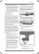
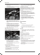
fig 1
1
2
3
3
12
12
77
9
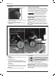
Get to know your compressor
Please refer to g 1, 2 and 3.
1. TANK DRAIN VALVE
(located on bottom of tank) - The tank drain
valve can be opened to allow moisture and
compressed air to be released from the air tank.
The tank drain valve should
always be opened slowly to
avoid damage to equipment and possible injury.
2. AIR TANK -
ten gallon (37.9 liters) tank
3. RUBBER FOOT
Reduces compressor vibration and movment.
4. SAFETY VALVE -
The safety valve automatically relieves pressure
from the air tank in the event of excessive
pressure build up. Safety Valve is preset at
factory. Do not attempt to make any adjustments
to the safety valve. Periodically pull the ring on
WARNING
the safety valve end to check that it is working
properly.
5. RESERVOIR AIR PRESSURE GAUGE -
Indicates pressure of compressed air built up in
the tank.
6. PRESSURE SWITCH -
Controlled by the red-tipped power switch lever
which turns the air compressor on and o . When
switch lever is pulled up, compressor is turned
o . When lever is moved down to the "Auto"
position, the pressure switch is engaged and will
start the compressor pump automatically when
tank pressure is below the factory-set minimum.
The pressure switch continues to monitor the
pressure and turns the pump o when the
pressure reaches the factory-set maximum.
Always make sure that the
compressor power switch is in the
OFF position before performing any maintenance
or plugging the compressor into a power supply.
NOTICE