06.12 product manual H-4114SD.
Contents First Steps with Your Electrical Density Gauge............................. 1 Turning on the Battery Pack......................................................... 1 Registering Your EDG................................................................... 2 Components................................................................................. 2 Soil Model Calibration Preparation.............................................. 6 Producing a Soil Model................................................
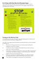
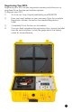
First Steps with Your Electrical Density Gauge Upon opening your Electrical Density Gauge (EDG), you will see the following card attached to the face panel of the gauge. Read the card and follow the instructions. 1 STOP BEFORE YOU USE YOUR EDG Turn the Battery On! 2 Register your EDG! Your EDG was shipped with the battery switched off and must be switched on before use. Registering your EDG initiates the product warranty and allows you to download future firmware and software updates.
Registering Your EDG Registering your EDG initiates the product warranty and allows you to download future firmware and software updates. To Register your EDG: 1) Go to this url: http://www.humboldtmfg.com/REGISTER 2) Enter your email address as your username; Enter the complete Registration Number located on the attached Registration Label.
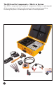
The EDG and Its Components— What's in the box Your EDG is comprised of a number of components. Below is a photograph of the components, check to make sure you have received everything. Following the photo is a description of each of the components.
1. The Case: The Electrical Density Gauge is built into its case, providing storage of all the gauge components allowing for easy transportation. The actual gauge is built into the right side of the case and accessories are stored on the left side except for the Dart Template, which is stored in the lid of the case. 2. Dart Template: The Dart Template is located in the lid of the EDG. It is secured with velcro to keep it in place. To remove unfasten the velcro straps. 3.
6. Battery Charger Cable In use, the EDG runs on battery power supplied by a Lithium Ion Battery. The battery provides about 60 hours of runtime from a fully charged battery. The battery needs to be charged periodically. To charge it, use the supplied cable located in the accessory caddy. To use, plug the Battery Charger Cable into an electrical outlet and plug the other end into the port at the top right of the EDG's control panel.
Soil Model Calibration Preparation In order to use the Electrical Density Gauge (EDG) to determine moisture, density and % compaction of materials, you must first develop what is called a Soil Model of the material(s) you wish to ultimately measure. Per ASTM D7698-11, a Soil Model is defined as: the result of a calibration procedure that establishes a correlating linear function between measured electrical soil properties and measured physical soil properties.
Select areas on the Job Site where the type of soil is consistent from place to place, and where there are differences in water content and compaction. Special preparation of spots of different densities or water contents should be done the day before, so as to allow stabilization of the soil water content.
3. You should be looking at a screen that looks like this: To begin, press the Projects button (Top right button with folder icon) on the Touch Screen or the Projects key on the Key Pad, You will see this screen: 6. To create a new Soil Model, press the NEW PROJECT key . A keyboard will be displayed entitled: New Soil Model Name. Use the keyboard to type in a name for your Soil Model in the Value Field.
7. Type in a name for this Soil Model, which can be up to 8 characters long, i.e. soil type, date, location, test reference number, etc. 8. Press the Select button to save the Soil Model you have created. 9. Once saved, a screen with your soil model name will appear with no data; stating: "No Soil Tests Available". 10. On this screen, press the Model Details button right of the screen.
If you already have Proctor data for the material you are going to be testing, enter the Maximum Dry Density and the Optimum Moisture in the appropriate fields. Simply press the appropriate field and a keyboard will appear for you to enter data into the field. The screen shots below show adding a value to the Max Dry Density field. Once you've entered data, press the Select button will be saved to the field. and your info Now you can add a value to the Optimum Moisture field.
In actual testing, The Maximum Dry Density and the Optimum Moisture data will be used by the EDG to generate % compaction results. Next press the Classify button at the bottom left of the screen. A scrolling list of the Unified Soil Classification descriptions will appear. Find the soil classification that best fits the material you are testing, click on it to highlight it and press the Done button at the bottom right to choose this description.
11. Upon pressing the Apply button screen: , you will see the following Press the Save button , you will see the following screen: (Or you can press the Cancel button .
Press the Green Select button which selects the Soil Model for use and Turns the Green Dot to Gray . Press the Done button you will see the following screen: , 12. To continue to build a Soil Model, Make sure the name of your Soil Model on the left is selected, which will highlight the name of the Soil Model in blue. By selecting this specific Soil Model, any tests performed while it is selected will be linked to this specific Soil Model.
13. You are now ready to begin building your Soil Model. To accomplish this you will need: The EDG and its test accessories, as well as one of the following traditional test method apparatus: a. Nuclear Gauge b. Sand Cone c. Voluvessel d.
14. What you are trying to accomplish by building a soil model is to develop a curve, which illustrates the density and moisture characteristics of the material you wish to ultimately test. This curve will be comprised of a series of tests (typically 6 to 12 tests) of the material at different levels of compaction effort and different levels of moisture, which when completed will produce a curve used by the EDG to provide accurate readings of density and moisture.
16. To begin, place the gauge on the ground near you and open the case. a. Turn the gauge on, and remove the gray, circular Dart Template from the lid of the case. b. Place the gray, circular template on the ground. Remove the accessory caddy from the EDG case and place it on the ground, out of the way. Remove the Hammer and the four Darts from the bottom of the case. Position the Darts at the detents on the gray template and pound them into the ground with the Hammer.
17. You are now ready to begin running your first test for your Soil Model. If you are already at the screen below from the previous step, simply press the Test button at the bottom right of the screen to begin a test. NOTE: If you have turned the gauge off and transported it to a test site, when you turn the gauge back on, it will default to the last chosen Project/Soil Model you were previously working with, which will return you to the screen above.
Press the Perform Electrical Test button . Once this is done the Gauge will perform a test and the next window will appear, telling you to switch the connectors on the Darts to the B and B position. The diagram on the screen below illustrates the correct position of the darts to use. Press the Perform Electrical Test button . The Gauge will now perform a second test and the next window will appear. At this point you can ignore the numbers in green and the reference to FIT.
18. Now that you have conducted your first test in developing your Soil Model, you will also need to run a test on the same spot using the traditional density and moisture test method you have chosen to use in conjunction with the EDG. Complete this test and maintain the results for entering the results into the EDG. If the method you have chosen to use provides results on-site, like a nuclear gauge, you can enter the results into the EDG as you build your soil model.
You will see the following Screen. On the left is a scrolling list of the soil tests you made with the EDG. Select each one at a time and fill in the corresponding data for Wet Density and Moisture Content, which you recorded with your traditional method testing apparatus at each test location.
When you have completed this step, DO NOT PRESS THE SAVE BUTTON. Continue entering the Wet Density and Moisture values from your traditional method tests into each of the corresponding Soil Tests you have run with the EDG. From the Screen above, choose each point in the Soil Tests list on the left and enter the Wet Density and Moisture data for each Test in the same manner as you just did the first one. Once you have completed entering the information for all your points. Press the Save button .
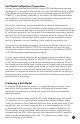
22. Once your Soil Model is completed, you can view the Graphs (Curves), which make up the Soil Model. To view the Graphs, press the Graphs button at the bottom left of the screen next to the Trash button. There are actually two Graphs, which make up your Soil Model. The first is the Impedance vs. Wet Density Graph. This Graph should appear similar to this: The second Graph is Weight of Water vs. C/R, which you can view by pressing the Next Graph button on the top right of the screen.
23. Graph Refinement and Fit Adjustment Each point (soil test) on either Graph (Curve) can be evaluated. To do this use the Back and Forward Arrows at the Top right of the Screen. Using the Arrows, cycles you through the different Points on the Graph, and the corresponding number of the current point is shown between the buttons. The current selected point will be highlighted as a green box on the Graph. See Screen below: In addition, each individual point of the Graph can be Enabled or not.
By turning off outlying point 1 on the Graph, the Curve is redrawn and the FIT improves to 0.732, as shown in the Graph below. This creates a much tighter and more accurate Curve, which will result in more accurate readings when using the EDG.
To close this screen, press the Done button to this screen: , which will return you At this point your Soil Model is complete, press the Back button to return to the Soil Model Testing Screen. Remember, over time, you can always add points to the your Soil Model to make it more accurate. To do this you would select the Soil Model you want to alter and follow the steps beginning with Step 12. .
24. Performing Soil Tests To begin Soil Testing with the EDG, if you are still on the screen below after completing your soil model, press the Back button . You will see the home screen below: And, If you have turned the gauge off before beginning your Soil Testing, you will also see this screen. Press the Job Sites button with the blue helmet. You will see this screen: From this screen, create a new Job Site by pressing the Add button in the lower left of the screen.
A keyboard will appear. Type a name for your Job Site and press the Select button . You've now created a Job Site and need to assign a soil model to it. To do this, press the Soil Model Selection button at the lower left of the screen below. Until you actually select a soil model the Selected Soil Model Field will say UNSELECTED. To select a Soil Model, press the drop-down menu under Choose Soil Model: and choose the Soil Model you wish to assign to this Project.
Remember: Once a Soil Model has been selected (linked) for a Job Site, it cannot be changed. Press the Ok button . Notes: Warning: Once a Soil Model is linked with a job site and saved, it can not be changed. Also note that changes to the soil model will not take affect on the current Job Site. Essentially what this means, is that once you link a Soil Model to a specific Job Site, the data in that Soil Model in relationship to this specific Job Site is frozen.
On this screen, you can see your Job Site at the top: and, at the bottom, in red, the Soil Model you have linked to it. Press the Save button . You will see the following screen. You can select this as your working Project by clicking on the green Select button at the bottom right of the screen. The Select Button will turn gray, indicating it is selected.
25. You are now ready to begin actual testing at your jobsite. Testing follows the same process you used to create your soil model, except that you won't need the traditional methods anymore. So to begin, place the gauge on the ground near you and open the case. a. Turn the gauge on, and remove the gray, circular Dart Template from the lid of the case. b. Place the gray, circular template on the ground. Remove the accessory caddy from the EDG case and place it on the ground, out of the way.
to have as straight a run as possible. The Cables should not cross. Care should be taken not to cross the Cables when asked to switch them from the A-A position to the B-B position during the testing process. e. Remove the Thermistor (Temperature Sensor), located in its plastic case, in the accessory caddy. Plug the Thermistor (Temperature Sensor) into the mini-phone plug port located on the side of the Sensor Unit directly above where the Black cable enters.
Press the Perform Electrical Test button . Once this is done the Gauge will perform a test and the next window will appear, telling you to switch the Dart positions to the B and B position. The diagram on the screen below illustrates the correct position of the darts to use. Press the Perform Electrical Test button . The Gauge will now perform a second test and the next window will appear. This window shows the results of your test. To save your results, Press the Save button .
You will see the following Screen. From this screen, after each test you will see the Test Results. You can also review the results of individual Soil Tests by Pressing the Arrow Keys at the bottom of the screen. The number between the Arrows indicates which test the results above it correspond to. Using the Arrows, cycles you through the completed tests you have conducted for this Job Site.
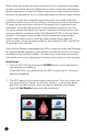
Pressing the Data button following screen: will present you with the The EDG features Blue Tooth Capabilities, So if you computer works with Blue Tooth enabled hardware, you can access the data in your EDG and transfer it to your computer for use with the EDG software. To be able to import data to your computer via Blue Tooth, you must turn on the Blue Tooth Connection. This is accomplished by Pressing the ON next to Blue Tooth Connection.
To transfer data via USB, insert a USB thumb drive into the USB slot. The thumb drive must be formatted in Base 16 format or it may not work. Base 16 is the default formatting within Windows® 7. When transferring data from the EDG, you have your choice of Exporting Job Sites, Exporting Soil Models or Exporting All. You make your choice by pressing the corresponding button on the Communication screen. You can also use the USB device and port to import Soil Models from other gauges or previous Projects.
Next, press the Test button on the screen below. If your gauge passes the calibration check test, you will see the screen above.
30. Firmware Upgrade Firmware upgrades will be available. When one is available, you will get an email to the email address you used when you registered your Gauge. This email will include a link, from which you will be able to download the Firmware upgrade to your computer. To install this Firmware upgrade, copy it from your computer to a USB thumb drive. Take this thumb drive and inset it into the EDG's USB port, located on the Faceplate.
You will see the following screen: Press the Update button and follow the directions. The Gauge's Power light will flash green, when you have completed the Update process.
EDG Screen Icons Takes you to the Soil Models Screen where you can create and store Soil Models data Takes you to the Job Sites Screen where you can create and store Job Sites data Takes you to the Data Screen where you can transfer data to and from the EDG Takes you to the Setup Screen where you can set Date, Time, Engineering info, Humboldt Contact data OK or Select buttons. Used to select current Soil Model or Job Site. When selected circle is gray. Also used to OK information typed into keyboards.
Humboldt Mfg. Co. 875 Tollgate Road Elgin, Illinois 60123 U.S.A. Testing Equipment for U.S.A. Toll Free: 1.800.544.7220 Voice: 1.708.456.6300 Fax: 1.708.456.0137 Email: hmc@humboldtmfg.com Construction Materials HUMBOLDT www.humboldtmfg.