1.
this is a blank page corrector
Description When combined with appropriate electrodes (pins) and test leads, the H-4385 can be used to measure earth resistance or the resistance-to-earth of a buried electrode, such as a ground rod or an anode, for example.
2) When the approximate resistance (say of the local soil) is not known, move the range selector switch (labeled “Ohms Multiply By”) to the 100K setting and position the “Balance Dial” knob at “10”. 3) Pull the “Null Sensitivity” switch down to the “Low” position and note that the null indicating meter needle moves to the right, indicating too high a resistance setting. 4) While holding the “Null Sensitivity” switch in the “Low” position, step down through the resistance ranges (10K, 1K, 100Ω etc.
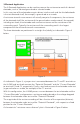
So, for example, if the H-4385 produces a resistance value of 15 ohms for an electrode (pin) spacing of 20 feet, the earth’s average resistivity value to a depth of 20 feet would be: ρ = 191.5 x 20 x 15 = 57,450 ohm.cm If the resistivity value is required to be expressed in ohm.m, rather than ohm.cm, the ohm.cm value is divided by 100. In the above example, the resistivity would be 574.5 ohm.
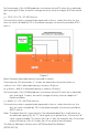
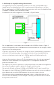
2. Soil Sample (or Liquid) Resistivity Measurement This application also uses 4 electrodes, however, in this case, the electrodes are an integral part of an electrolyte box, which is more commonly referred to as a soil box. For this application, the H-4385 can be used in conjunction with one a Humboldt soil box (H-4386 or H-4386SM) and 4 test leads (H-4388). A schematic of the test arrangement is illustrated in Figure 2 below.
3-Electrode Application The 3-Electrode Application can be used to measure the resistance-to-earth of a buried electrode, such as a buried ground rod or a buried anode. In this case, two of the electrodes are pins driven into the earth and the third electrode is the test electrode itself, for example, a ground rod or an anode.
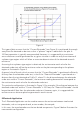
Figure 4 This type of plot assumes that the “Current Electrode” (see Figure 3) is positioned far enough away from the electrode under test so that a “plateau” region is obtained in the plot. A 100 foot separation is typically recommended. However, it is suggested that a resistance versus distance curve be generated for any given situation in order to verify the existence of a plateau-type region which will allow an accurate determination of the electrode-to-earth resistance.
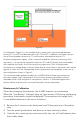
Figure 5 As indicated in Figure 5, in this configuration, jumper wires are connected between terminals C1 and P1 and between terminals C2 and P2. In addition, test leads connect one of the electrodes to terminal C1 and the other electrode to terminal C2. Another configuration option, which is recommended for use when measuring small resistances, is to connect the potential terminals (P1 and P2) directly to the electrodes with separate test leads, thus eliminating the jumper wires.
4) Insert 4 new C-size alkaline batteries into each holder tube and reinstall the tubes making sure that the battery polarity is correct (as labeled) in each case. 5) Re-install the retaining clips. 6) Re-install the panel into its plastic case and re-install the 4 screws on the front side of the panel. With respect to calibration, it is recommended that the H-4385 be re-calibrated on an annual basis.
Warranty Humboldt Mfg. Co. warrants its products to be free from defects in material or workmanship. The exclusive remedy for this warranty is Humboldt Mfg. Co., factory replacement of any part or parts of such product, for the warranty of this product please refer to Humboldt Mfg. Co. catalog on Terms and Conditions of Sale. The purchaser is responsible for the transportation charges. Humboldt Mfg. Co.