
User Manual


2) Whentheapproximateresistance(sayofthelocalsoil)isnotknown,movetherange
selectorswitch(labeled“OhmsMultiplyBy”)tothe100Ksettingandpositionthe
“BalanceDial”knobat“10”.
3) Pullthe“NullSensitivity”switchdowntothe“Low”positionandnotethatthenull
indicatingmeterneedlemovestotheright,indicatingtoohigharesistancesetting.
4) Whileholdingthe“NullSensitivity”switchinthe“Low”position,stepdownthrough
theresistanceranges(10K,1K,100etc.)untiltheneedlemovestotheleftofthenull
position (left of the center position) and then step back up one range.
5) Adjustthepositionofthe“BalanceDial”untiltheneedleispositionedatthenull
(center) location on the meter.
6) Multiplythe“BalanceDial”settingbytherangesetting(settingontheswitchlabeled
“OhmsMultiplyBy”)toobtaintheresistancevalue.Forexample,fora“BalanceDial”
settingof4.5andarangeswitchsettingof100,theresistancevalueis450
7) Applytheresistancevaluetothecalculationofresistivityusingtheappropriate
formulaforyourapplication(seetheApplicationssectionbelow).
Note:Youcanincreasethesensitivityoftheresistancereadingbyholding
the“NullSensitivity”switchinthe“High”positionandnetuningthe
balance,afterndingthebalancepointinthe“Low”sensitivityposition.
Applications
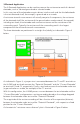
4-electrode Applications
1.EarthResistivityMeasurement
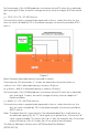
Thisapplicationuses4electrodes(pins).Theelectrodesaredrivendownintothe
earththesamedistanceandareevenlyspacedinastraightline.
AschematicofthisarrangementisillustratedinFigure1below.
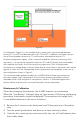
TheH-4385canbeusedinconjunctionwiththe4-lead(color-coded)testreeland
fourheavy-duty(stainlesssteel)electrodes(soilpins)–(H-4388).Thetestleadsare
connectedtotheH-4385asshowninFigure1.Withthisarrangement,theH-4385
effectivelymeasurestheearth’saverageresistancetoadepthequaltotheelectrode
spacing (S).
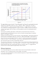
Dr.FrankWenneroftheU.S.BureauofStandardsdevelopedthetheorybehindthis
testin1915[1].Heshowedthat,iftheelectrode(pin)depth(d)iskeptsmallrelative
totheseparationbetweentheelectrodes(S),theearth’saverageresistivitytoadepth
equaltotheelectrodespacing(S)canbeobtainedbyapplyingthefollowingformula:
whereRistheresistancevalueinohmsasdeterminedusingtheH-4385,istheresistivity
in ohm.cm, istheconstant3.1416,andSistheelectrodeseparationincm.
Typically,theelectrode(pin)spacingisnotmeasuredincentimetersbut,rather,infeet(in
theU.S.)orinmeters(inmostothercountries).
U.S.Example(electrodespacingmeasuredinfeet):
Sincethereare30.38centimetersin1foot,theaboveformulacanbewrittenas:
= 2x30.38x(electrodespacinginfeet)xR(ohms),or
=191.5x(electrodespacinginfeet)xR(ohms)