
User Manual

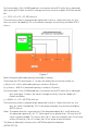
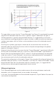


Thistypeofplotassumesthatthe“CurrentElectrode”(seeFigure3)ispositionedfarenough
awayfromtheelectrodeundertestsothata“plateau”regionisobtainedintheplot.A
100footseparationistypicallyrecommended.However,itissuggestedthataresistance
versusdistancecurvebegeneratedforanygivensituationinordertoverifytheexistenceof
aplateau-typeregionwhichwillallowanaccuratedeterminationoftheelectrode-to-earth
resistance.
Assumingthataplateau-typeregionisobtained,theresistance-to-earthvalueforthe
electrodeundertestwillbetheresistancevalueontheplotcorrespondingtotheplateau
regionasillustratedinFigure4.
Ageneralrule-of-thumb,whichassumesthatthe“CurrentElectrode”ispositionedsufciently
farawayfromtheelectrodeundertest,isthatifthe“PotentialElectrode”ispositionedata
distancefromthetestelectrodeof0.62xD,whereDisthedistancebetweentheelectrode
undertestandthe“CurrentElectrode”,theresistancereadingobservedwillcorrespondto
theresistance-to-earthvaluefortheelectrodeundertest.
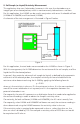
ThisparticularcongurationisillustratedinFigure3.Forexample,ifthedistancebetweenthe
electrodeundertestandthe“CurrentElectrode”is100feet,the“PotentialElectrode”should
bepositioned62feetfromtheelectrodeundertest.However,again,itissuggestedthat
resistanceversusdistanceplotsbegeneratedineachinstance.
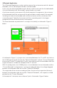
2-Electrode Application
The2-ElectrodeApplicationcanbeusedtomeasuretheresistancebetweentwoburied
electrodes, such as two ground rods, or two anodes, for example.
Inthiscase,thetwoelectrodesarethetwoburiedcomponents.Figure5belowillustratesthe
measurementconguration.
Figure4