2.
TABLE OF CONTENTS Introduction............................................................................................1 Applications Product Use Product Description General Warnings....................................................................... 2 Safety Warnings Electrical Warnings Manufacturer’s Rights and Responsibilities................................ 2 Software Copyright Important Notice .............................................................................. 3 Updated products.......
Input Configuration......................................................................... 14 Configuring Input............................................................................ 15 Sensor Min...................................................................................... 16 Sensor Max...................................................................................... 16 Calibration................................................................................ 17 Device ID...............
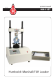
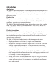
Introduction 1 Applications The HM-1327 Marshall Loader is designed specifically for running Marshall and TSR tests. Its modular design minimizes initial costs and allows easy upgrades. And with array of connectivity options, data presentation has never been easier. Product Use This product is intended for use only in accordance with the directions and specifications contained in this User Guide.Your HM-1327 has been configured according to your specifications.
• 2 Plug and play Serial port (RS232) communications with Humboldt Material Testing Software (HMTS) for controlling and HM Download Software for downloading machine run test data. In addition, the loader offers a large, backlit LCD display, a touch-sensitive keypad, a battery-backed real time clock, and auto-conversion of calibration and speed parameters between English and SI units. General Warnings Safety Warnings Operators should take care to operate this machine under the maximum load restrictions.
3 The programmable, read-only memory, integrated circuit package contained in this equipment and covered with a copyright notice label contains proprietary and confidential software, which is the sole property of HUMBOLDT MFG. CO. It is licensed for use by the original purchaser of this equipment for a period of 99 years. Transfer of the license can be obtained by a request, in writing, from HUMBOLDT MFG. CO.
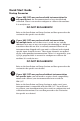
Quick Start Guide 4 Startup Scenarios 1 If your HM-1327 was purchased with instrumentation for one specific test: the instrumentation has been installed and calibrated. There is no need to configure or calibrate the machine. It is ready for use. DO NOT RECALIBRATE! Refer to the Installation and Setup Section and then proceed to the section for the specific test desired.
Installation and Set-up 5 Unpacking Initial inspection should include checking for physical damage during shipping and obvious external damage to the product. Package contents are defined by your packing list. Each Marshall Loader is configured according to customer specifications. In your inspection, make certain that the contents of your shipment match the documentation provided by your packing list.
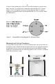
6 If you are using third-party cables for load cells/transducers connections, make sure they are wired to be compatible with the HM-1327. Consult Figure #1 for a compatible reference wiring diagram. Plugs to connect third-party instrumentation to the Humboldt HM-1327 are available, order part HM-000474. Pin3= +dc Output Pin4= –dc Output Figure 1.
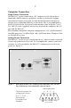
7 Computer Connection Single Device Connection The HM-1327 can be connected to a PC computer to take advantage of Humboldt’s HMTS software capabilities, conduct real time data logging and enhanced report generation, or with the HM Download Software to download tests performed directly on the device.This is accomplished via the RS-232 port on the back panel of the machine (refer to Figures 7 & 8.). Use a RS-232 cable (supplied) and attach it between the computer’s RS-232 port and the HM-1327.
Operation 8 Power Switch The Power Switch is located in the back panel on the rear of the machine above the electrical cord inlet. Also, located between the electrical cord inlet and the Power Switch is the Fuse Compartment. The HM-1327 uses a 10 amp fuse. To begin operation, press the Power Switch. Fuse Compartment. Figure 10. HM-1327 Power Switch, Electrical Cord Inlet and Fuse Compartment. Key Functions Figure 11.
9 Set Up Key Pushing the Set Up Key brings up the main set up screen from which you can run a test, review your last test, access the engineering set up menus and set the date, time, units, standards criteria. This key also is used to return to a previous screen. Up Key Pushing the Up Key allows you to move the platen up to facilitate testing. When the key is pushed the green light next to it is lit. Stop Key Pushing the Stop Key stops platen movement.
10 Set-up Functions Set Date To set the Date press until you see this screen: * REVIEW LAST TEST * RUN TEST * MORE SETUP Press you will see this screen: * ENGINEERING SETUP * SENSOR LIMITS * RAW_DATA * MORE SETUP Press OFF you will see this screen: * RECALL CALIBRATION * CHANGE DEVICE ID * MORE SETUP Press you will see this screen: * DATE/UNIT/STANDARD * MANUFACTURERS INFO. Press (DATE/UNIT/STANDARD).
11 Press (CHANGE DATE).You should see this screen: * DATE = "MM/DD/YY" * INCREASE * DECREASE Press (DATE) to select the month/date/year. Press (INCREASE) or Press (DECREASE) to change the appropriate number.
Press 12 (DATE/UNIT/STANDARD).You should see this screen: * CHANGE DATE * CHANGE TIME * UNIT = ENGLISH/METRIC * STANDARD = ASTM/BS Press (CHANGE TIME).You should see this screen: * TIME = "HH/MM/SS" * INCREASE * DECREASE Press (TIME) to select the HOURS/MINUTES/SECONDS. Press (INCREASE). or Press (DECREASE) to change the appropriate number.
13 Press you will see this screen: * DATE/UNIT/STANDARD * MANUFACTURES INFO Press (DATE/UNIT/STANDARD).You should see this screen: * CHANGE DATE * CHANGE TIME * UNIT = ENGLISH/METRIC * STANDARD = ASTM/BS Press (units) to toggle between English and Metric Units. Select the standard desired—the flashing standard is the active choice.
14 Press you will see this screen: * DATE/UNIT/STANDARD * MANUFACTURERS INFO. Press (DATE/UNIT/STANDARD).You should see this screen: * CHANGE DATE * CHANGE TIME * UNIT = ENGLISH/METRIC * STANDARD = ASTM/BS Press (STANDARD) to toggle between ASTM and BRITISH STANDARD. Select the standard desired—the flashing standard is the active choice.
15 Press (CONFIGURATION) You will be asked for a password, enter: You should see this screen: CONFIGURATION screen * SELECT INPUT "CHI" * CONFIGURE CHANNEL Press (SELECT INPUT) to scroll through and choose the input you wish to configure. Once you have selected a channel press (CONFIGURE INPUT).You should see this screen: INPUT 1 NAME SENSOR MIN *SENSOR MAX CONFIGURE = STAB = 0 = 10000 Configuring Input The Configuration screen will allow us to configure the Sensor Max value.
16 Sensor Min The Sensor Zero (SENSOR MIN) is not configurable and is set at 0. Sensor Max Press (SENSOR MAX) to set the Sensor Maximum value. You should see this screen: “CH1” MAX SETUP * SENSOR MAX = * INCREASE * DECREASE “000000” Press (SENSOR MAX) to move between the numbers. Keep pressing until the digit you want to change is flashing. Once you have selected the number you want to change, press (INCREASE) or (DECREASE) to change the number to the desired value.
17 Calibration This menu item is used to calibrate or verify the calibration of the HM-1327. WARNING: Calibration should only be performed by trained personnel with proper, certified equipment. The HM-1327 and its instrumentation should be calibrated once a year or as the need arises.
18 (SELECT INPUT) to scroll through and choose the channel you Press wish to calibrate. Once you have chosen the desired channel you wish to calibrate press (CLEAR CALIBRATION). WARNING: IF YOU CLEAR A CALIBRATION IT IS LOST FOREVER! After the calibration has been cleared, Press You should see this screen: INPUT CALIBRATION * SET GAIN * SET SENSOR MIN * SET SENSOR MAX (CALIBRATE CHANNEL) 1 123 12345 Press (SET GAIN).
19 Humboldt Calibration Instrumentation Chart Load Cell Part# 10,000 lb. (50kN) HM-2300.100 5,000 lb. (25kN) HM-2300.050 2,000 lb. (10kN) HM-2300.020 1,000 lb. (5kN) HM-2300.010 500 lb. (2.5kN) HM-2300.005 LVDT Transducer 0.4" (10.0mm) HM-2310.04 1.0" (25.4mm) HM-2310.10 2.0" (50.8mm) HM-2310.20 Pore Pressure 100psi (1000kPa) HM-2300.
20 * RECALL CALIBRATION * CHANGE DEVICE ID Press (CHANGE DEVICE ID).You should see this screen: DEVICE ID = 1 * INCREASE * DECREASE Press to increase the ID number or press to decrease the number. Once the ID has been changed, press to go back to previous menu. Note: Up to 16 devices can be connected to a single computer. SENSOR LIMITS Sensor upper limits can be set to ON or OFF.
Standard Tests 21 Marshall Center the breaking head on the platen. Press the button to raise the head to the start position, close to the load cell. There should be about a 1/8" (3.000mm) gap between the breaking head and the load cell. Press You should see this screen: * REVIEW LAST TEST * RUN TEST * MORE SETUP Press (RUN TEST) You should see this screen: * MARSHALL TEST * TSR TEST Press (MARSHALL TEST) This will automatically start the platen to rise at a rate of 2.0 in/min (50.8mm/min).
22 You should see this screen: STAB PEAK “#” FLOW PEAK “#” REVIEW DATA * RUN MARSHALL TEST Peak values are shown on the first two lines. To review all the data, press (REVIEW DATA).You should see this screen: * PRINT DATA * SCROLL DATA * RUN MARSHALL TEST Pressing (PRINT DATA) will print the data to a printer or save a file in ASCII mode to your computer using Humboldt Material testing Software (HMTS) or Windows Hyper terminal.
Software 23 The HM-1327 comes with Humboldt’s HMTS data collection software. This software can be used to collect data from tests by creating user-defined test parameters (start/stop). The resulting data can then be opened in Microsoft Excel to view the data collected, as well as create a simple table and graph. Optional pre-defined reporting software modules and templates are available for specific tests, such as CBR,Triaxial, etc.
24 Specifications Applicable Standards Covers: Marshall Tests ASTM: D6927 and D4123-82 AASHTO:T245 and T283 BS 598: Part 107 Mechanical Specifications Dimensions (l x w x h) Platen Travel Net Weight Shipping Weight Speed Range Load capacity Vertical clearance Horizontal clearance 17 x 22 x 42 inch (432 x 559 x 1295mm) 3 inches (76mm) Max. 206 lbs. (94kg) 300 lbs. (660kg) 2 inches/min (51mm/min) 11000 lbs. (50 kN) 24 inch (610mm) Max. 11.
25 Support Phone support is available for general operating questions and trouble shooting problems between 8am and 5pm Eastern Time. Please call: 1.800.537.4183 1.919.832.6509 or fax: 1.919.833.5283 support@humboldtmfg.com For sales and sales-related information, such as available accessories, general sales questions, pricing, please call: 1.800.544.7220 1.708.456.6300 or fax: 1.708.456.0137 hmc@humboldtmfg.
NOTES 26
NOTES 27
10 Humboldt Mfg. Co. 875 Tollgate Road Elgin, Illinois 60123 U.S.A. Testing Equipment for U.S.A. Toll Free: 1.800.544.7220 Voice: 1.708.456.6300 Fax: 1.708.456.0137 Email: hmc@humboldtmfg.com Construction Materials HUMBOLDT www.humboldtmfg.