07.08 product manual HM-3000.
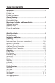
TABLE OF CONTENTS Introduction............................................................................................1 Applications Product Use Product Description General Warnings....................................................................... 2 Safety Warnings Electrical Warnings Manufacturer’s Rights and Responsibilities................................ 2 Software Copyright Important Notice .............................................................................. 3 Updated products.......
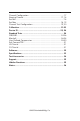
Channel Configuration.................................................................... 17 Naming Channel....................................................................... 17, 18 Set Min............................................................................................ 18 Set Max..................................................................................... 18, 19 Channel Test Configuration....................................................... 19, 20 Calibration.......................
Introduction 1 Applications The HM-3000 Series MasterLoader Compression Testing Frame is designed for applications requiring multi-purpose loading systems. It is ideal for Geotechnical laboratories, road construction projects, educational institutions, and start-up laboratories. Its modular design minimizes initial costs and allows easy upgrades as desired. Product Use This product is intended for use only in accordance with the directions and specifications contained in this User Guide.
• • 2 Plug and play Serial port (RS232) communications with Humboldt Material Testing Software (HMTS) for controlling and downloading stored data. Unique ID and RS485 communication port for multiple unit connections with a single computer. In addition, the loader offers a large, backlit LCD display, a touch-sensitive keypad, a battery-backed real time clock, and auto-conversion of calibration and speed parameters between English and SI units.
3 The programmable, read-only memory, integrated circuit package contained in this equipment and covered with a copyright notice label contains proprietary and confidential software, which is the sole property of HUMBOLDT MFG. CO. It is licensed for use by the original purchaser of this equipment for a period of 99 years. Transfer of the license can be obtained by a request, in writing, from HUMBOLDT MFG. CO.
Quick Start Guide 4 Startup Scenarios 1 If your HM-3000 was purchased with instrumentation for one specific test: the instrumentation has been installed and calibrated. There is no need to configure or calibrate the machine. It is ready for use. DO NOT RECALIBRATE! Refer to the Installation and Setup Section and then proceed to the section for the specific test desired.
Installation and Set-up 5 Unpacking Initial inspection should include checking for physical damage during shipping and obvious external damage to the product. Package contents are defined by your packing list. Each MasterLoader is configured according to customer specifications. In your inspection, make certain that the contents of your shipment match the documentation provided by your packing list.
6 If you are using third-party cables for load cells/transducers connections, make sure they are wired to be compatible with the HM-3000. Consult Figure #1 for a compatible reference wiring diagram. Plugs to connect third-party instrumentation to the Humboldt HM-3000 are available, order part HM-000474. Pin3= +dc Output Pin4= –dc Output Figure 1.
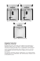
7 Figure 4. Unconfined Setup Figure 5. UU Triaxial Setup Figure 6. TSR/Soil Cement Setup Computer Connection Single Device Connection The HM-3000 can be connected to a PC computer to take advantage of Humboldt’s HMTS software capabilities, conduct real time data logging and enhanced report generation. This is accomplished via the RS-232 port on the back panel of the machine (refer to Figures 7 & 8.). Use a RS-232 cable (supplied) and attach it between the computer’s RS-232 port and the HM-3000.
8 Multi Device Connection Multi devices, such as HM-3000s, HM-2325A, HM-2330D MiniLoggers, HM2560A, HM-2700A, HM-2700D Direct shear Apparatus can be connected to a computer via the HM-3000’s RS-485 port. This allows you to daisy-chain several devices to the same computer; require HM-000375 (RS232 to RS485 converter not included). Use a standard CAT 5 cable (not included) to link the additional device’s output port to the HM-3000’s RS-485 input port (refer to Figures 7 & 8).
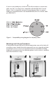
9 CAT 5 Cable RS-232 to RS-485 converter (HM-000375) Figure 8. Diagram illustrating computer and multiple device connections. Figure 9. Back Panel electronic board showing location of Dip switches for setting Computer connections. For single device setups, set Dip Switch #4 to on (default setting). For multiple device setups, set Dip Switch #4 to off.
Operation 10 Power Switch The Power Switch is located in the back panel on the rear of the machine above the electrical cord inlet. Also, located between the electrical cord inlet and the Power Switch is the Fuse Compartment. The HM-3000 uses a 10 amp fuse. To begin operation, press the Power Switch. Fuse Compartment. Figure 10. HM-3000 Power Switch, Electrical Cord Inlet and Fuse Compartment. Key Functions Figure 11.
11 Set Up Key Pushing the Set Up Key brings up the main set up screen from which you can run a test, review your last test, access the engineering set up menus and set the date, time, units, standards criteria. This key also is used to return to a previous screen. Speed Key Pushing the Speed Key allows you to set the test speeds of the machine. Up Key Pushing the Up Key allows you to move the platen up to facilitate testing.
12 Set-up Functions Set Date To set the Date press until you see this screen: * REVIEW LAST TEST * RUN TEST * MORE SETUP Press you will see this screen: * ENGINEERING SETUP * SENSOR LIMITS * RAW_DATA * MORE SETUP Press OFF you will see this screen: * RECALL CALIBRATION * CHANGE DEVICE ID * DATE/UNIT/STANDARD * MANUFACTURES INFO Press (DATE/UNIT/STANDARD).You should see this screen: * CHANGE DATE * CHANGE TIME * UNIT = ENGLISH/METRIC * STANDARD = ASTM/BS Press (CHANGE DATE).
13 Set Time To set the Time press until you see this screen: * REVIEW LAST TEST * RUN TEST * MORE SETUP Press you will see this screen: * ENGINEERING SETUP * SENSOR LIMITS OFF * RAW_DATA * MORE SETUP Press you will see this screen: * RECALL CALIBRATION * CHANGE DEVICE ID * DATE/UNIT/STANDARD * MANUFACTURES INFO Press (DATE/UNIT/STANDARD).You should see this screen: * CHANGE DATE * CHANGE TIME * UNIT = ENGLISH/METRIC * STANDARD = ASTM/BS Press (CHANGE TIME).
14 Set Units To set the Units the HM-3000 will use to display results, press you see this screen: until * REVIEW LAST TEST * RUN TEST * MORE SETUP Press you will see this screen: * ENGINEERING SETUP * SENSOR LIMITS OFF * RAW_DATA * MORE SETUP Press you will see this screen: * RECALL CALIBRATION * CHANGE DEVICE ID * DATE/UNIT/STANDARD * MANUFACTURES INFO Press (DATE/UNIT/STANDARD).
15 * REVIEW LAST TEST * RUN TEST * MORE SETUP Press you will see this screen: * ENGINEERING SETUP * SENSOR LIMITS OFF * RAW_DATA * MORE SETUP Press you will see this screen: * RECALL CALIBRATION * CHANGE DEVICE ID * DATE/UNIT/STANDARD * MANUFACTURES INFO Press (DATE/UNIT/STANDARD).You should see this screen: * CHANGE DATE * CHANGE TIME * UNIT = ENGLISH/METRIC * STANDARD = ASTM/BS Press (STANDARD) to toggle between ASTM and BRITISH STANDARD.
16 (SPEED) to move between the numbers. Keep pressing Press until the digit you want to change is flashing. Once you have selected the number you want to change, press (INCREASE) or (DECREASE) to change the number to the desired value.
17 Channel Configuration If you are adding new instrumentation, changing existing instrumentation or reconfiguring the HM-3000’s channel setup, you need to configure the channel for use with the devices you have. To configure a channel, press You should see this screen: * REVIEW LAST TEST * RUN TEST * MORE SETUP Press you will see this screen: * ENGINEERING SETUP * SENSOR LIMITS OFF * RAW_DATA * MORE SETUP Press (ENGINEERING SETUP).
18 “CH1” CONFIGURATION * NAME = “CH1” * INCREASE * DECREASE Press (INCREASE) or (DECREASE) repeatably to scroll through the available channel names for an appropriate choice. Choices for channel names are: CH1, CH2, CH3, CH4, LOAD1, LOAD2, LOAD3, LOAD4, DISP1, DISP2, DISP3, DISP4, FLOW, STAB, VERT, HORZ, PRES1, PRES2, PRES3, PRES4, VOLU1, VOLU2, VOLU3 and VOLU4.
19 (SENSOR MAX) to move between the numbers. Keep pressing until the digit you want to change is flashing. Once you have selected the number you want to change, press (INCREASE) or (DECREASE) to change the number to the desired value. Below is a configuration chart for Humboldt instrumentation. These are the numbers that correspond to each Humboldt sensors. Press Load Cell Part# English Max (lbf) Metric Max (kN) 10,000 lb. (50kN) HM-2300.100 010000 050.00 5,000 lb. (25kN) HM-2300.
Press 20 (ENGINEERING SETUP).You should see this screen: * CONFIGURATION * CALIBRATION * LOGGING INTERVAL Press (CONFIGURATION) You will be asked for a password, enter: You should see this screen: CONFIGURATION screen * SELECT CHANNEL “CH1” * CONFIGURE CHANNEL * CONFIGURE TEST Press (SELECT CHANNEL) to scroll through and choose the channel you wish to configure test for. Once you have selected a channel press (CONFIGURE TEST).
21 Calibration This menu item is used to calibrate or verify the calibration of the HM-3000. WARNING: Calibration should only be performed by trained personnel with proper, certified equipment. The HM-3000 and its instrumentation should be calibrated once a year or as the need arises.
22 (SELECT CHANNEL) to scroll through and choose the channel Press you wish to calibrate. Once you have chosen the desired channel you wish to calibrate press (CLEAR CALIBRATION). WARNING: IF YOU CLEAR A CALIBRATION IT IS LOST FOREVER! After the calibration has been cleared, Press You should see this screen: CH1 CALIBRATION * SET GAIN * SET SENSOR MIN * SET SENSOR MAX (CALIBRATE CHANNEL) 1 123 12345 Press (SET GAIN).
23 Humboldt Calibration Instrumentation Chart Load Cell Part# 10,000 lb. (50kN) HM-2300.100 5,000 lb. (25kN) HM-2300.050 2,000 lb. (10kN) HM-2300.020 1,000 lb. (5kN) HM-2300.010 500 lb. (2.5kN) HM-2300.005 LVDT Transducer 0.4" (10.0mm) HM-2310.04 1.0" (25.4mm) HM-2310.10 2.0" (50.8mm) HM-2310.20 Pore Pressure 100psi (1000kPa) HM-2300.
24 * RECALL CALIBRATION * CHANGE DEVICE ID * DATE/UNIT/STANDARD * MANUFACTURES INFO Press (CHANGE DEVICE ID).You should see this screen: DEVICE ID = 1 * INCREASE * DECREASE Press to increase the ID number or press to decrease the number. Once the ID has been changed, press to go back to previous menu. Note: Up to 16 devices can be connected to a single computer. SENSOR LIMITS Sensor upper limits can be set to ON or OFF.
25 * REVIEW LAST TEST * RUN TEST * MORE SETUP Press (RUN TEST) You should see this screen: * MARSHALL TEST * CBR/LBR TEST * USER DEFINED TEST Press (CBR/LBR TEST) You should see this screen: MOTOR SPEED ADJUST * SPEED= “0.00000” * INCREASE * DECREASE Press (SPEED) to access the speed readout on line 2 of the screen above. Keep pressing until the digit you want to set is flashing.
26 NOTE: If you apply all the surcharge weight in the mold at the beginning of the test, just Press to continue. The HM-3000 will start the test. The display will show the current reading of the load and displacement. The HM-3000 will collect a load reading every 0.025 inches. Once the displacement reaches 0.5 inches, the machine will stop collecting data and reverse the platen back to the lower limit at 2.0 in/min (50.8 mm/min). At any time you can press to end the test.
27 * REVIEW LAST TEST * RUN TEST * MORE SETUP Press (RUN TEST) You should see this screen: * MARSHALL TEST * CBR/LBR TEST * USER DEFINED TEST Press (MARSHALL TEST) This will automatically start the platen to rise at a rate of 2.0 in/min (50.8mm/min).You should see this screen: MARSHALL TEST # of readings STAB “#” FLOW “#” * END TEST The display above will give constant real-time readings of the stability and flow measurements during the test cycle.You can end the test at any time by pressing .
28 Peak values are shown on the first two lines. To review all the data, press (REVIEW DATA).You should see this screen: * PRINT DATA * SCROLL DATA * RUN MARSHALL TEST Pressing (PRINT DATA) will print the data to a printer or save a file in ASCII mode to your computer using Humboldt Material testing Software (HMTS) or Windows Hyper terminal.
Press 29 You should see this screen: * REVIEW LAST TEST * RUN TEST * MORE SETUP Press (RUN TEST) You should see this screen: * MARSHALL TEST * CBR/LBR TEST * USER DEFINED TEST Press (USER DEFINED TEST).You should see this screen: MOTOR SPEED ADJUST * SPEED = “X.XXXX” * INCREASE * DECREASE Press (SPEED) to access the speed readout on line 2 of the screen above. Keep pressing until the digit you want to set is flashing.
30 Once the load cell has reached its peak load and fallen 2%, the HM-3000 will stop collecting data and reverse the platen to its down position at the fast rate 2.0 in/min (50.8mm/min). The peak load will be displayed. You should see this screen: LOAD 1 PEAK DISP 1 PEAK * REVIEW DATA * RUN TEST “#” “#” Peak values are shown on the first two lines. To review all the data, press (REVIEW DATA).
31 SOIL-CEMENT See User-Defined Unconfined Compression, without the displacement transducer selected in the test configuration TSR See User-Defined Unconfined Compression, without the displacement transducer selected in the test configuration UU Triaxial See User-Defined Unconfined Compression CU Triaxial See User-Defined Unconfined Compression, plus add third channel for Pore Pressure into test configuration.
Software 32 The HM-3000 comes with Humboldt’s HMTS data collection software. This software can be used to collect data from tests by creating user-defined test parameters (start/stop). The resulting data can then be opened in Microsoft Excel to view the data collected, as well as create a simple table and graph. Optional pre-defined reporting software modules and templates are available for specific tests, such as CBR,Triaxial, etc.
33 Specifications Applicable Standards Covers: CBR, UU, CU, CD, UC, Marshall and Hveem Tests ASTM: D1883, D2850, D2166, D4767 and D5581 and D6927 AASHTO:T193,T296,T297,T208,T245 and T246 BS 1377: Part 4: 1990, BS 1377: Part 7: 1990, BS 1377: Part 8: 1990, BS 598: Part 107 Mechanical Specifications Dimensions (l x w x h) Platen Travel Net Weight Shipping Weight Speed Range Load capacity Vertical clearance Horizontal clearance 17 x 19 x 59 inch (430 x 480 x 1500mm) 4 inches (100mm) Max. 240 lbs.
Test Accessories 34 HM-3001—California Bearing Ratio (CBR) Accessory Set: HM-2300.100 Load cell 10,000 lb. (50 kN) HM-2310.10 Displacement Transducer 1.0”(25mm) HM-4178BRT Displacement Transducer Bracket H-4178 CBR Plunger HM-3001SW CBR /LBR Reporting software HM-3002—Unconsolidated Undrained (UU) Triaxial Accessory Set: HM-2300.020 Load cell 2,000 lb. (10 kN) HM-200387 Ball seat adapter HM-2310.20 Displacement Transducer 2.
35 Support Phone support is available for general operating questions and trouble shooting problems between 8am and 5pm Eastern Time. Please call: 1.800.537.4183 1.919.832.6509 or fax: 1.919.833.5283 support@humboldtmfg.com For sales and sales-related information, such as available accessories, general sales questions, pricing, please call: 1.800.544.7220 1.708.456.6300 or fax: 1.708.456.0137 hmc@humboldtmfg.
NOTES 36
Humboldt Mfg. Co. 875 Tollgate Road Elgin, Illinois 60123 U.S.A. Testing Equipment for U.S.A. Toll Free: 1.800.544.7220 Voice: 1.708.456.6300 Fax: 1.708.456.0137 Email: hmc@humboldtmfg.com Construction Materials HUMBOLDT www.humboldtmfg.