product manual 12.
Introduction: This manual covers the installation and operation of Humboldt FlexPanels for Triaxial and Permeability testing. This equipment comes in different configurations but is essentially built from two basic units. The equipment is packaged for easy installation, which allows you to be up and running as quickly as possible. The primary intention of this manual is to guide the first-time user of FlexPanels through the familiarization and installation of the equipment.
Functional Overview Purpose of Equipment The panels are used to control pressure and monitor flow of liquids in and out of various testing apparatus. The device can be used with other equipment to perform these ASTM procedures: D4767, D2850, D5084 and other international standards. How equipment can be used: • To back-pressure saturate a specimen. • Monitor consolidation or swell (volume change) • Control pressure and monitor volume change during a shear test.
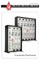
HM-4160 HM-4150 HM-4140 fig. 1 The HM-4140, HM-4150 and HM-4160 Distribution Panels all use the same control section, which is essentially a HM-4140 Master Controller. No matter which panel you are using, the controls will work the same. See the following pages for explanations of the different panels and controls. HM-4150A HM-4160A fig. 2 The HM-4150A and HM-4160A Distribution Panels are add-on panels, which can be used with any of the Controller Panels in fig.
The Master Controller The Master Controller (Fig. 3) can be used as a stand-alone controller (HM-4140) for controlling functions when used in conjunction with HM-4150A and HM-4160A Distribution Panels. Master Controller 1 PRESSURE AIR SUPPLY INCREASE 2 VACUUM SUPPLY INCREASE DEAIRED WATER TANK VACUUM OFF 3 PRESSURE FILL OFF DRAIN TAP WATER OFF 4 DEAIRED WATER OUTPUT PRESSURE OFF VACUUM OUTPUT fig.
The Master Controller can also be used as an integral part of the HM-4150 and HM-4160 Distribution Panels (Fig. 4). In all cases, the Master Controller functions in the same way.
Master Controller Functions The Master Controller is shown in fig. 3 and fig. 4. The different sections of the Controller are numbered to reference the drawings and the operation of each is explained below. 1 2 This is the digital display, which allows you to read the current cell, base or top pressures from up to 5 different cells, depending upon your particular configuration.
FlexPanel Control Burette Groups Humboldt FlexPanel Controls are organized into groups consisting of three, control burettes, each of which can be used to regulate pressure or volume changes. Models HM-4150 and HM-4150A provide one group of control burettes and Models HM-4160 and HM-4160A provide two groups of control burettes.
Group Controls— Section 1 A1 The Selection Valve (A1) at the top of the section selects the type of pressure input for the top of the burette assembly. It can select VACUUM (Regulated), VENT (to atmosphere), OFF (closed) or PRESSURE (controlled by the Regulator below it). The Pressure Regulator (R1) supplies a regulated pressure for the burette assembly in this section. The regulator in section 1 is different than the regulators in sections 2 and 3.
F1 The Fill/Drain Valve (F1) is used to fill and drain the Burette Assembly (B1). To fill either the External or the Burette chambers, the External Valve (C1) or the burette value (V1) are opened. If a line is connected to the QuickConnect (C1) when filling or draining, the Valve on the cell end should be closed. Turn the valve to Drain very slowly and the Burette or External Burette Chamber will drain to a waste container or a drain line. To use the Fill setting, the burette assembly must be vented.
Models HM-4150A and HM-4160A are Add-on panels, which can be used with any of the Control Panels. The HM-4150A provides the controls for one cell and the HM-4160A provides controls for two.
Installation and Configuration The contents of this section will guide the user through the proper steps required to safely install and hook up the Panel. This section should be read in its entirety for first-time installers and reviewed during the installation process. Equipment Set-up The first thing, after taking the panel out of the carton, is to place the panel(s) on a level work surface capable of supporting the unit(s) and providing sufficient room in which to work and service the panels later.
Connecting Utilities Located on the back of each FlexPanel is one or two service connector plates. These connector plates are used to connect utilities to the panels (Figure 7). Twenty feet of 1/4-inch plastic tube has been supplied for service connections. Rear of Control Panels (HM-4140, HM-4150, HM-4160) showing Lower and Upper Service Connector Plates. Also shows plugs used in exit connector for Pressure and Readout when not using Add-On Panel.
Control Panel Connections (HM-4140, HM-4150, HM-4160): (1/4-inch tubing is used for connections) 1) Install a section of tubing from the air supply to the PRESS IN connector on the lower service connector plate. 2) Install a section of tubing from the water line to the TAP connector on the lower service connector plate. 3) Install a section of tubing from the water side of the de-aired water tank to the DEAIRED connector, marked de-aired on the lower service connector plate.
Operation This section discusses the use of FlexPanels when running a typical test. Refer to Figure 8 on next page) Master Controller The individual functions of the Master Controller are reviewed below. Digital Display The Digital Display provides a readout of the cell, base or top pressures of an individual test cell. To read a pressure, raise the toggle valve (T1, T2 or T3), located under the regulator for the section you wish to check.
Selection Valve Sections A2 1 2 Master Controller A1 Selection Valve Pressure Regulator R2 Pressure Regulator R1 Toggle Valve Toggle Valve 3 HM-4150 Distribution Panel VACUUM PRESSURE OFF VENT VACUUM OFF PRESSURE VENT PRESSURE VACUUM OFF PRESSURE INCREASE INCREASE T2 INCREASE INCREASE CELL PRESSURE BASE PRESSURE R3 Pressure Regulator T3 Toggle Valve BV Bridge Valve E3 Extenal Valve TOP PRESSURE VACUUM SUPPLY INCREASE BA Selection Valve AIR SUPPLY T1 Bias Valve A3
To make De-aired water, assuming a Nold De-aired unit or a De-aired water tank has been connected to the panel, following these steps: 1. Set the vacuum regulator to highest vacuum level. 2. Turn the Deaired Water Tank Valve in Section 3 of the Master Controller to vacuum, which applies a vacuum to the De-aired Water Tank. 3. Fill the tank about three quarters full with water by turning the Fill/Drain Valve to Fill. Once the tank is filled, turn valve to Off. 4.
The pressure should be checked and adjusted after approximately 15 minutes and then checked periodically when taking readings on from the Burettes. Toggle Valve The Toggle Valves are all connected in a series of tees, leading to the Digital Display on the Control Panel. When the Toggle Valve is lifted, the pressure for the adjacent Control Burette is indicated on the Digital Display. Only one Control Burette pressure can be read at one time.
Fill and Drain Valves This valve located at the bottom of each of the Control Burette Sections and is used to fill and drain the Internal and External Burettes of the Burette Assemblies. To Fill, the Burette or External Valves need to be open to fill that portion of the Burette Assembly. The water to fill the Burette Assembly comes from the Deaired Water Port on the Lower Service Connector Plate. The Burette Assembly can not be filled unless the top is vented by turning the Selection Valve to vent.
Allow the Internal Burette to fill about 3/4 full, then turn the Fill/Drain Valves (F1, F2, F3) and the Burette Valves (V1, V2, V3) to off. It is now assumed the Burette Assemblies are filled with De-aired Water. Flushing Lines from Panel to Cell Before setting up a sample in the Triaxial Cell, allow water to flow through the Top and Base tubes to flush air out of the lines.
Applying Initial Cell Pressure The following steps should be followed when applying the initial cell pressure before starting back pressure saturation. 1) If the sample length is being monitored take a reference reading before applying pressure to cell. 2) Turn the selection valve (A1) to the pressure position. 3) Lift the Toggle Valve (T1) and check the pressure setting of the pressure regulator (R1). 4) Those systems with a Master Control Panel can read the pressure on the Digital Display.
Back Pressure Saturate Sample The following steps should be followed to back pressure saturate the sample. 1) Turn the Selection Valve (A2) to Pressure. 2) Turn the Bias Valve to Bias On. 3) Turn the Burette Valve (V2) to Burette. 4) Turn the Selection Valve (A3) to off. 5) Turn the Bridge Valve (BV) to Bridge On. 6) Turn the Burette Valve (V3) to Burette. 7) Make sure the Top and Base Valves on the Triaxial cell, which are connected to the FlexPanel, are open.
5) Adjust the back pressure, lift Toggle Valve (T2) in section 2 (Base). Increase pressure by an increment of 5, 10 or 20 psi (35, 70, or 140 kpa). 6) Take Pore Pressure Transducer reading. Monitor for 1 to 2 minutes. 7) Open the Top and Base Drainage Valves on base of Triaxial Cell. 8) Determine the "B" parameter: ∆m B = ∆d 3 ∆m = Change in pore pressure ∆d3= Change in cell pressure The water being pushed into sample can be monitored on Burettes in Sections 2 (Base) and 3 (Top).
3) Place cell in load frame and take reading on pore pressure transducer. 4) Take other appropriate steps outlined in the ASTM Standard D4767 or any international standard. 5) For a undrained triaxial shear test, close the Drainage Valves on the bottom of the Triaxial Cell, not those going to the pressure transducer. Hydraulic Conductivity of Triaxial Sample The following steps can be taken after back pressure saturation or consolidation to set the panel up for Hydraulic Conductivity.
Humboldt Mfg. Co. 875 Tollgate Road Elgin, Illinois 60123 U.S.A. Testing Equipment for U.S.A. Toll Free: 1.800.544.7220 Voice: 1.708.456.6300 Fax: 1.708.456.0137 Email: hmc@humboldtmfg.com Construction Materials HUMBOLDT www.humboldtmfg.