PiranhaMAX 165, 175, 176i, 195c, & 196ci Installation and Operations Manual 532030-1_A
Thank You! Thank you for choosing Humminbird®, the #1 name in Fishfinders. Humminbird® has built its reputation by designing and manufacturing top-quality, thoroughly reliable marine equipment. Your Humminbird® accessory is designed for trouble-free use in even the harshest marine environment.
NOTE: Some features discussed in this manual require a separate purchase, and some features are only available on international models. Every effort has been made to clearly identify those features. Please read the manual carefully in order to understand the full capabilities of your model. NOTE: The illustrations in this manual may not look the same as your product, but your unit will function in the same way. NOTE: To purchase accessories for your control head, visit our web site at humminbird.
Table of Contents Installation Overview 1 Fixed Control Head Installation 2 Determine Where to Mount . . . . . . . . . . . . . . . . . . . . . . . . . . . . . . . . . . . . . . . . . 2 Connect the Power Cable to the Boat . . . . . . . . . . . . . . . . . . . . . . . . . . . . . . . . . 2 Assemble the Control Head Base . . . . . . . . . . . . . . . . . . . . . . . . . . . . . . . . . . . . . 4 Route the Control Head Cables Under the Deck . . . . . . . . . . . . . . . . . . . . . . . . .
Table of Contents Moving the Portable Fishfinder 34 Power ON and OFF 35 PiranhaMAX Sonar Technology 36 Single Beam Sonar . . . . . . . . . . . . . . . . . . . . . . . . . . . . . . . . . . . . . . . . . . . . . . . 37 Dual Beam Sonar. . . . . . . . . . . . . . . . . . . . . . . . . . . . . . . . . . . . . . . . . . . . . . . . . 37 What You See on the Display 38 How GPS Works 39 The PiranhaMAX Control Head 40 Key Functions 41 POWER/MENU Key . . . . . . . . . . . . . . . . . . . . . . . . . .
Table of Contents Sonar Menu 52 View . . . . . . . . . . . . . . . . . . . . . . . . . . . . . . . . . . . . . . . . . . . . . . . . . . . . . . . . . . . 53 Depth Range . . . . . . . . . . . . . . . . . . . . . . . . . . . . . . . . . . . . . . . . . . . . . . . . . . . . 53 Sensitivity. . . . . . . . . . . . . . . . . . . . . . . . . . . . . . . . . . . . . . . . . . . . . . . . . . . . . . . 53 Zoom . . . . . . . . . . . . . . . . . . . . . . . . . . . . . . . . . . . . . . . . . . . . . . . . . . . .
Installation Overview Before you start installation, we encourage you to read these instructions carefully in order to get the full benefit from your PiranhaMAX. There are three basic installation tasks that you must perform for the PiranhaMAX: • Installing the Control Head • Installing the Transducer • Testing the complete installation and locking the transducer position.
Fixed Control Head Installation 1. Determine Where to Mount Begin the installation by determining where to mount the control head. Consider the following to determine the best location: • To check the location planned for the control head, test run the cables for the power and transducer. See Transom Transducer Installation in order to plan the location of the transducer and cable route.
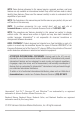
POSITIVE NOTE: Humminbird® is not responsible for over-voltage or over-current failures. The control head must have adequate protection through the proper selection and installation of a 1 amp fuse. GROUND Figure 3 1a. If a fuse terminal is available, use crimp-on type electrical connectors (not included) that match the terminal on the fuse panel. Attach the black wire to ground (-), and the red wire to positive (+) 12 VDC power (Figure 3). Install a 1 amp fuse (not included) for protection of the unit.
3. Assemble the Control Head Base Your control head base will have a tilt and swivel mount. See the instructions below to assemble and mount the control head base. To assemble a tilt and swivel mount: Tilt and Swivel Mount Control Head Base Assembly Mount Arms Base 1. Insert the mount arms into the base. Then, hold the mount arms in place as you turn the base upside down. 2. Insert the swivel ring into the base, with the countersink holes for the arm screws facing out. 3.
4. Route the Control Head Cables Under the Deck Use the following steps to route the control head cables under the deck. NOTE: Under the deck cable routing is not always possible. If this is not an option, the cables should be routed and secured above deck. NOTE: See Transom Transducer Installation in order to plan the location of the transducer and cable route. Tilt and Swivel Mount Control Head Base Tilt and Swivel Mount: 1a. Mark and drill a 3/4" hole as shown in Figure 6.
5. Attach the Control Head to the Base Follow these steps to attach the control head to the already-assembled base: NOTE: The transducer cable and power cable should be routed prior to securing the mounting bracket to the deck. 1. Apply marine-grade silicone sealant to the drilled holes for the mounting bracket. 2. Place the mounting bracket on the mounting surface, aligning with the drilled holes. 3. Insert the four #8 Phillips countersink wood screws into the mounting holes.
5. Align the pivot knuckle with the mount base arms and slide into place, twisting slightly if necessary, until the unit is firmly seated. 6. Rotate the control head to the desired angle and hand tighten the thumbknob bolt. 7. Thread the gimbal knob onto the pivot bolt and tighten. 6. Attach the Cables to the Control Head Follow these steps to attach the power and transducer cables to the control head: 1.
Transom Transducer Installation Overview Following are instructions for transom mount installation. The transom mount installation provides the least loss of signal since the transducer is mounted outside the hull. This installation also allows adjustment of both running angle and depth after the transducer is mounted, which enables you to tune the installation for best results. NOTE: Due to the wide variety of hulls, only general instructions are presented in this installation guide.
Transom Transducer Installation 1. Locate the Transducer Mounting Position Turbulence: You must first determine the best location on the transom to install the transducer. It is very important to locate the transducer in an area that is relatively free of turbulent water.
transducer out of the water at higher speeds. The transducer must remain in the water for the control head to maintain the sonar signal (Figure 10). • If the transom is behind the propeller(s), it may be impossible to find an area clear from turbulence, and a different mounting technique or transducer type should be considered, such as an Inside the Hull Transducer.
Positioning the Mounting Bracket Level Level Figure 13 Boat Hull Types Require Different Mounting Positions 1. Make sure that the boat is level on the trailer, both from port to starboard and from bow to stern, by placing your level on the deck of the boat, first in one direction, then in the other. 2. Hold the mounting bracket against the transom of the boat in the location you have selected (Figure 13). Align the bracket horizontally, using the level.
4. Make sure that the drill bit is perpendicular to the actual surface of the transom, NOT parallel to the ground, before you drill. Using a 5/32” bit, drill the two holes only to a depth of approximately 1”. NOTE: On fiberglass hulls, it is best to use progressively larger drill bits to reduce the chance of chipping or flaking the outer coating. 3.
Measuring the Transom Angle Plumb Line Transom Angle in degrees (°) Weight Measured Distance (X) 2. Place the two ratchets, one on either side of the transducer knuckle, so that the beads on each ratchet line up with the desired position number on the knuckle (Figure 18a). If you are setting the ratchets at position 1, the beads on each ratchet will line up with the rib on the transducer knuckle to form one continuous line on the assembly (Figure 18b). NOTE: The ratchets are keyed.
Inserting the Pivot Bolt 3. Put the pivot bolt through the assembly to hold it in position and loosely install the nut, but do NOT tighten the nut at this time (Figure 19). CAUTION! Do not use a high speed driver on this combination of fasteners. Hand tighten only. Figure 19 Mounting the Assembly to the Transom 4. Align the mounting bracket transducer assembly with the drilled holes in the transom.
6. Adjust the transducer assembly vertically, until the seam on the leading edge of the transducer (the edge closest to the transom of the boat) is level and just slightly below the hull (Figure 23). Adjusting the Transducer Mounting Position NOTE: The transducer has a natural downward slant of 4-5 degrees from leading edge (closest to the boat transom) to trailing edge (farthest away from the boat). Looking at the back of the transducer, the seam should be slightly below the bottom of the hull.
4. Route the Cable The transducer cable has a low profile connector, which must be routed to the point where the control head is mounted. There are several ways to route the transducer cable to the area where the control head is installed. The most common procedure routes the cable through the transom into the boat. NOTE: Your boat may have a pre-existing wiring channel or conduit that you can use for the transducer cable. 1. Unplug the other end of the transducer cable from the control head.
Routing the Cable 3. Place the escutcheon plate over the cable hole and use it as a guide to mark the two escutcheon plate mounting holes. Remove the plate, drill two 9/64" diameter x 5/8" deep holes, and then fill both holes with marinegrade silicone sealant. Place the escutcheon plate over the cable hole and attach with two #8 x 5/8" wood screws. Hand tighten only! 4. Route and secure the cable by attaching the cable clamp to the transom.
5. Test and Finish the Installation Once you have installed both the control head and the transom transducer, and have routed all the cables, you must perform a final test before locking the transducer in place. Testing should be performed with the boat in the water. 1. Press POWER once to turn the control head on. If the unit does not power up, make sure that the connector is fully plugged into the terminal slot and that power is available. 2.
NOTE: It is often necessary to make several incremental transducer adjustments before optimum high speed performance is achieved. Due to the wide variety of boat hulls, however, it is not always possible to obtain high speed depth readings. 6. Once you have reached a consistently good sonar signal at the desired speeds, you are ready to lock down the transducer settings.
PiranhaMAX Portable Case Assembly It is important to perform the PiranhaMAX portable case assembly tasks in order, referring to the step-by-step procedures that represent the following main assembly tasks: • Assembling the PiranhaMAX mount • Assembling the base and handle • Assembling the control head to the base and handle • Routing the cables in the base • Assembling the portable case • Charging and installing the battery • Assembling the transducer mounting bracket • Stowing the portable transducer and b
1. Assemble the Control Head Base Your control head base will have a tilt and swivel mount. See the instructions below to assemble and mount the control head base. To assemble a tilt and swivel mount: Tilt and Swivel Mount Control Head Base Assembly 1. Insert the mount arms into the base. Then, hold the mount arms in place as you turn the base upside down. Mount Arms Base 2. Insert the swivel ring into the base, with the countersink holes for the arm screws facing out. 3.
2. Assemble the Base and Handle In this procedure, you will install the PiranhaMAX mount and handle to the base of the portable case. Punching Holes 1. Turn the base upside down. Punch out the mounting holes labeled “C” with a hammer and a screwdriver (or an awl) as shown in the illustration Punching Holes. 2. Turn the base right side up. Line up the PiranhaMAX mount with the holes you punched out in step 1. 3.
4. Install the handle onto the base, so that the curved part of the handle faces towards the back of the base, towards the battery well. Use the four included #8-32 x 7/16" screws, two on each side, to attach the handle to the base (see the illustrations Installing the Handle Onto the Base and Sliding in the Handle). Hand tighten only! Sliding in the Handle Installing the Handle Onto the Base Figure 31 NOTE: The handle is keyed so that it only fits onto the base in one direction. 3.
Attaching the Control Head to the Base and Handle Pivot Knuckle Thumbknob Bolt Gimbal Knob Gimbal Knob Rear View Front View Figure 32 4. Route the Cables In this procedure, you will route the power and transducer jumper cables on the underside of the base, and attach the tiedown straps that will be used to secure the battery to the base in a later procedure. 1.
2. Route the power cable from the mount DOWN through the center hole of the base. Route the transducer jump cable UP through the base and mount. (Figure 34) Pulling the Cables Through the Base 3. Connect the cables to the control head. The slots for the plugs are keyed to prevent reverse installation, and insertion should be easy. Do not to force the connectors into the control head. (Figure 35) 4.
6. Fit the transducer jumper cable connector down into the jumper cable well and snap it into place. Insert the two #6-32 x 1/4" screws included to secure the transducer jumper connector and tighten using a Phillips screwdriver. Hand tighten only! 7. Secure all cables to the base, using the included zip ties, at the mount points shown in the illustration (see the illustration Tying Down the Cables). Tying Down the Cables Zip Tie Mounting Point Transducer Jumper Cable Power Cable Figure 37 8.
5. Assemble the Portable Case In this procedure, you will install the base assembly into the portable case. 1. Unzip the largest opening on the front of the portable case. 2. Insert the base assembly into the portable case, so that the PiranhaMAX control head is facing out of the case. For best results, pull the case over one shoulder of the handle at a time. 3. Adjust the case so that you can easily grab the handle, through the fabric handhold inset, from the outside top of the portable case.
Installing the Battery Tying Down the Battery Figure 39 3. Pull the two battery tie-down straps over the top of the battery and connect both ends of each strap over the top, making sure that the straps are pulled tight around the battery and that the battery is seated securely in the battery well. 4. Zip up the back opening. NOTE: Do NOT connect the power cable to the battery at this time. You should wait until just before fishing to connect the power cable to the battery. 7.
2. Assemble the other transducer parts as shown (see the illustration Assembling the Portable Bracket below). Hand tighten only! Assembling the Portable Bracket Suction Cup Portable Transducer Assembly Phillips Head Screw Washer Bolt Wing Nut Ratchet Figure 41 NOTE: If you are unable to ratchet the transducer so that it rests below the water and points straight down, you can disassemble it and align the beads with a different number until you reach a position that allows the proper alignment.
Installing the Portable Case on the Boat Since the portable case has a large non-skid mounting surface, it may be attached to almost any surface. In this section, you will route the cables on the boat, connect the transducer and power cables to the portable case, and attach the portable case to a dry and convenient location on your boat. 1. Connect the Transducer and Power Cables to the Portable Case 1.
3. Turn the portable case around so that you can access the back, and open the back zipper. Connect the spade clip on the red wire of the power cable to the red terminal on the battery, and the spade clip on the black wire of the power cable to the black terminal on the battery. Make sure that the spade clips are snugly attached to the terminals (see the illustration Connecting the Spade Clips). 4.
Mounting the Portable Transducer Once your Portable fishfinder is fully assembled (see the Portable Case Assembly section for more information), it takes just a few easy steps before you are ready to fish: • Test the transducer prior to installation • Mount the portable transducer on the boat 1. Test the Transducer Prior to Installation Prior to installation, test the transducer to make sure that no damage occurred during shipping. 1.
NOTE: If you are trolling, it is best to mount the transducer on the transom of the boat. 1. Mount the transducer so that it points straight down and so that the transducer itself is submerged in the water (see the illustration Portable Transducer Mount). Transducer Running Angle Portable Transducer Mount Figure 44 2. Adjust the running angle so that the transducer is parallel to and below the surface of the water (see the illustration Transducer Running Angle). 3.
Moving the Portable Fishfinder You should take the portable case with you when you leave the boat and will not be using it. Perform the following steps to make your unit mobile: 1. With the boat engine off, loosen all cable retainers/clips holding the transducer. 2. Remove the case from the surface mount. 3. Remove the transducer from the surface where it has been mounted, wipe it dry, and stow it in the portable case rear pocket. 4. Unplug the power cable when not in use.
Power ON and OFF Use the following instructions to power on your PiranhaMAX unit: • Power On: Press the POWER/MENU key until the PiranhaMAX powers on, then release the key. • Start-Up Menu: When the PiranhaMAX powers on, the Start-Up menu temporarily appears. From this menu, select either Normal or Simulator. • For on the water use, select Normal. • To learn how to use the system with simulated data, select Simulator. • Power Off: Press and hold the POWER/MENU key until the unit powers off.
PiranhaMAX Sonar Technology The PiranhaMAX is the easiest to use fishfinder ever. For most anglers, all you’ll ever need to do is power on and fish! The PiranhaMAX automatically determines depth and makes adjustments to keep the bottom and fish visible on the display. The PiranhaMAX uses sonar technology to send sound waves from the transducer into the water.
Single Beam Sonar The PiranhaMAX 165 uses a 200 kHz single beam sonar system with a 28° area of coverage. Boat speed, wave action, bottom hardness, water conditions and transducer installation can all affect depth capability. Dual Beam Sonar The PiranhaMAX 175, 176i, 195c, and 196ci use a 200/455 kHz dual beam sonar system with a 28° area of coverage.
What You See on the Display The PiranhaMAX displays underwater information in an easy-to-understand format. The top of the display corresponds to the water surface at the transducer, and the bottom of the display corresponds to the Depth Range automatically selected for the current water depth. The Bottom Contour varies as the depth under the boat changes. Digital readouts provide precise information for depth, fish, and water temperature.
How GPS Works If your PiranhaMAX model includes GPS (Global Positioning System), it will use GPS and sonar to determine your current track, display it on a grid, and provide detailed underwater information. GPS uses a constellation of satellites that continually send radio signals to the earth. The GPS receiver on your boat receives signals from satellites that are visible to it. Based on time differences between each received signal, the GPS receiver determines its distance to each satellite.
The PiranhaMAX Control Head Your PiranhaMAX unit interface is easy to use. A combination of keys and special features allows you to control what you see on the display. Refer to the following illustration, and see Key Functions for more information.
Key Functions Your Fishfinder has a set of easy to use keys that give you flexibility and control over your fishing experience. POWER/MENU Key The POWER/MENU key is used to power the PiranhaMAX on and off. It is also used to open and close the menu system. • Menus: Press the POWER/MENU key in any view to open the menu for that view. Each menu provides frequently-used menu settings that correspond with the current view. • Menu Option Settings: Press the POWER/MENU key to confirm a menu option setting.
CHECK/ENTER Key The CHECK/ENTER Key has multiple functions, which depend on the view, menu, or situation. • Menu Activation: Press the CHECK/ENTER key after selecting a menu option to activate the menu or open a submenu. NOTE: See How to Use the Menu System for more information. • Menu Option Settings: Press the CHECK/ENTER key to confirm a menu option setting. The changes will be activated and saved immediately.
How to Use the Menu System Review the instructions below to understand how to use the menu system. 1. Open the Menu System Press the POWER/MENU key. 2. Select a Menu Option Press the UP or DOWN Arrow key to select a menu option. NOTE: Available menu options will be determined by the view currently displayed on-screen. See Views for more information. The menu name will be highlighted, indicating the menu is active, but the menu option is inactive.
Adjust a Menu Setting: After a menu is selected, press the UP or DOWN Arrow keys to adjust the menu setting. Press the CHECK/ENTER key or the POWER/MENU key to confirm the selection. Menu settings are saved and removed from the screen automatically after several seconds. NOTE: In Normal operating mode, most menu settings saved to memory will not return to their default values when the unit is turned off.
Set Up the Control Head Use the Setup Menu to customize the settings of your PiranhaMAX unit. • Set Sonar View Display Settings: Use the Setup Menu to set the Contrast, Bottom View, and how fish are displayed on-screen. • Set Units of Measurement: From the Setup Menu, open the Units submenu to set the units of measurement for distance and speed. See To Open the Units Submenu for instructions.
Contrast (PiranhaMAX 165, 175, and 176i models only) Settings: 1 to 5; Default = 3, Setting Saved in Memory Contrast accents the light and dark parts of the sonar data to provide greater definition. Fish ID+™ (Sonar View only) Settings: On, Off; Default = On, Setting Saved in Memory Dual Beam Single Beam Fish ID+™ uses advanced signal processing to interpret sonar returns, and will display a Fish Symbol when very selective requirements are met. To turn on fish symbols, select On.
Structure ID® represents weak returns as light pixels and strong returns as dark pixels. This has the benefit of ensuring that strong returns will be clearly visible on the display. Black (Bottom Black [monochrome models only]) displays all pixels below the bottom contour as black, regardless of signal strength. This has the benefit of providing a high contrast between the bottom and other sonar returns on the display.
Reset Settings: Select CONFIRM and press the CHECK/ENTER key to activate. Use this menu choice with caution! Reset restores ALL menu settings to their factory defaults. Language (International Models only) Settings Vary; Default = English, Setting Saved in Memory Language selects the display language for menus.
Views The sonar and navigation information from your Fishfinder are displayed on the screen in a variety of easy-to-read views. • Default View: When you first power up the control head, Sonar View will be the default view. • Available Views: The available views on your PiranhaMAX unit will vary with the model. See the following pages for more information. Display a View Use the instructions below to select a view to display on your PiranhaMAX control head. To Display a View: 1. Press the POWER/MENU key. 2.
Status View Status View displays current data, including the unit model number, serial number, and battery status. • PiranhaMAX models that include GPS will also display GPS data, such as GPS Fix, latitude and longitude, average satellite strength (CNO Avg.), and HDOP (the Horizontal Dilution of Precision). HDOP is a GPS system parameter which depends on the current satellite configuration. • Status Menu: From the Status Menu, you can change the view displayed on-screen. See Views for more information.
Sonar View Sonar View presents a historical log of sonar returns. The most recent sonar returns are charted on the right side of the display. As new information is received, the historical information scrolls left across the display. • Upper and Lower Depth Range numbers indicate the distance from the surface of the water to a depth range sufficient to show the bottom. • Sensitivity: Press the UP or DOWN Arrow keys to adjust the Sensitivity.
Sonar Menu Sonar Menu provides a shortcut to your most frequently-used settings in Sonar View. Sonar View must be displayed on the screen in order to open the Sonar Menu. From the Sonar Menu you can perform the following: • Customize the Sonar View Display: Set the Depth Range, Chart Speed, Zoom level, etc. NOTE: Menu options are determined by your Humminbird® model. See the following pages for full menu descriptions.
View Settings: Sonar, Track (PiranhaMAX 176i and 196ci only), Status; Default = Sonar View selects a view to be displayed on the screen. Depth Range Settings: Auto, 15 ft - 600 ft, 5 m - 184 m (International Models only); Default = Auto Depth Range sets the deepest depth range that will be displayed by the unit. Auto: When in automatic, the lower range will be adjusted by the unit to follow the bottom. Manual: You can adjust the Depth Range to lock the unit on a particular depth.
Zoom Settings: Off, Auto, Manual Ranges; Default = Off Zoom provides a magnified view of the bottom and structure. Auto: Select Auto to magnify the area around the bottom in order to reveal fish and structure close to the bottom that may not be visible during normal operation. When ZOOM is set to Auto, the upper and lower Depth Ranges are automatically adjusted to keep the area above and below the bottom on the display. Select Off to return to normal operation.
Filter Settings: On, Off; Default = Off, Setting Saved in Memory Filter adjusts the sonar filter to limit interference on the display from sources such as your boat engine, turbulence, or other sonar devices. Light Settings: 0 - 5; Default = 0 Light adjusts the brightness of the display. Use a higher backlight setting for night fishing. NOTE: Continuous backlight operation will significantly decrease the battery life for PiranhaMAX Portables.
Track View (PiranhaMAX 176i and 196ci only) Track View displays the current track (also known as the position history or breadcrumb trail) showing where the boat has been, along with saved waypoints. • Digital Readouts: The digital readouts in this view are fixed. • Zoom: Press the UP and DOWN Arrow keys to adjust the scale of the view. The zoom scale will be displayed on the screen. (See Track Menu: Zoom) • Mark Waypoints: Press the CHECK/ENTER key to mark the current position of the boat as a waypoint.
Track Menu (PiranhaMAX 176i and 196ci only) Track Menu provides a shortcut to your most frequently-used settings in Track View. Track View must be displayed on the screen in order to open the Track Menu. From the Track Menu you can perform the following: • Customize the Track View Display: Turn the COG Vector on or off, delete waypoints, start a new track, etc. NOTE: Menu options are determined by your Humminbird® model. See the following pages for full menu descriptions.
View Settings: Sonar, Track, Status; Default = Sonar View selects the current view displayed on the screen. Zoom Settings: Off, Manual Ranges; Default = Off Zoom adjusts the scale of the Track View. The zoom scale is indicated on the display as you adjust the setting. COG Vector Settings: Off, On; Default = On COG (Course Over Ground) Vector displays a line, extending from the bow of the boat, that projects your current course and shows where the boat will go if you continue on your present course.
Delete All Settings: Select CONFIRM and press the CHECK/ENTER key to activate. Use this menu choice with caution! Delete All allows you to delete all saved waypoints at one time. Light Settings: 0 - 5; Default = 0 Light adjusts the brightness of the display. Use a higher backlight setting for night fishing. NOTE: Continuous backlight operation will significantly decrease the battery life for PiranhaMAX Portables.
Alarms Alarms are based on the limits you set for a device, such as battery voltage, depth, and more. Set the alarms that apply to your PiranhaMAX installation and configuration. See the Alarms table for a complete list of PiranhaMAX alarms. To Set an Alarm: 1. Press the POWER/MENU key. 2. Select SETUP and press the CHECK/ENTER key. 3. Select ALARMS and press the CHECK/ENTER key. 4. Select an alarm and press the CHECK/ENTER key to activate the menu. 5.
Menu Alarm Name Alarm Description Range Sonar Menu: Alarms Mute Mute controls the audible sound made when an alarm is triggered. On, Off; Default = Off Battery Battery Alarm sounds when the input battery voltage is equal to or less than the menu setting. Off, 8.5V – 13.5V; Default = Off Fish Fish Alarm sounds when the fishfinder detects fish that correspond to the alarm setting.
Maintenance Your Humminbird® fishfinder is designed to provide years of trouble free operation with very little maintenance. Use the following procedures to ensure your Humminbird® continues to deliver top performance. Control Head Maintenance It is important to consider the following precautions when using your Humminbird® control head: • Chemicals, such as those found in bug spray and sunscreen, may cause permanent damage to the control head screen. Such damage is not covered by the warranty.
• If your boat remains out of the water for a long period of time, it may take some time to wet the transducer when it is returned to the water. Small air bubbles can climb to the surface of the transducer and interfere with proper operation. These bubbles dissipate with time, or you can wipe the face of the transducer with your fingers after the transducer is in the water.
Troubleshooting Do not attempt to repair the PiranhaMAX yourself. There are no user-serviceable parts inside, and special tools and techniques are required for assembly to ensure the waterproof integrity of the housing. Repairs should be performed only by authorized Humminbird® technicians. Many requests for repair received by Humminbird® involve units that do not actually need repair. These units are returned “no problem found.
the problem, inspect the transducer cable from end to end for breaks, kinks, or cuts in the outer casing of the cable. If the transducer is connected to the unit through a switch, temporarily connect it directly to the unit and try again. If none of these actions identifies an obvious problem, the transducer itself may be at fault. Be sure to include the transducer if returning the unit for repair. 4. When in very shallow water, I get gaps in the bottom reading and inconsistent digital depth indication.
PiranhaMAX 165 Specifications Depth Capability . . . . . . . . . . . . . . . . . . . . . . . . . . . . . . . . . . . . . .600 ft (183 m) Power Output . . . . . . . . . . . . . . . . . . . . . . . . . . . . . . . . . . . . . 200 Watts (RMS) 800 Watts (PTP) Operating Frequency . . . . . . . . . . . . . . . . . . . . . . . . . . . . .200 kHz Single Beam Area of Coverage . . . . . . . . . . . . . . . . . . . . . . . . . . . . . .28° @ -10 dB in 200 kHz Target Separation . . . . . . . . . . . . . . . . . . . . .
PiranhaMAX 175/176i/195c/196ci Specifications Depth Capability . . . . . . . . . . . . . . . . . . . . . . . . .200 kHz Beam: 600 ft (183 m) 455 kHz Beam: 320 ft (98 m) Power Output . . . . . . . . . . . . . . . . . . . . . . . . . . . . . . . . . . . . . .200 Watts (RMS) 1600 Watts (PTP) Operating Frequency . . . . . . . . . . . . . . . . . . . .200 kHz and 455 kHz Dual Beam Area of Coverage . . . . . . . . . . . . . . . . . . . . . . . . . . . . . .
Environmental Compliance Statement: It is the intention of Johnson Outdoors Marine Electronics, Inc. to be a responsible corporate citizen, operating in compliance with known and applicable environmental regulations, and a good neighbor in the communities where we make or sell our products. WEEE Directive: EU Directive 2002/96/EC “Waste of Electrical and Electronic Equipment Directive (WEEE)” impacts most distributors, sellers, and manufacturers of consumer electronics in the European Union.
Contact Humminbird® Contact the Humminbird® Customer Resource Center in any of the following ways: By Telephone: (Monday - Friday 8:00 a.m. to 4:30 p.m. Central Standard Time): 1-800-633-1468 By e-mail: (typically we respond to your e-mail within three business days): service@humminbird.