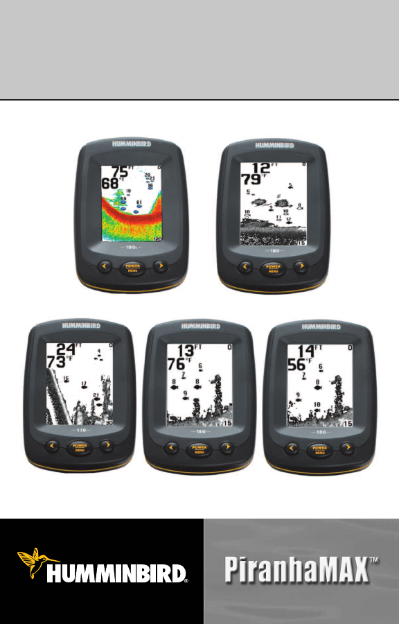
PiranhaMAX™ 150,160,170,180,190c Installation and Operations Manual 531678-1_B
Thank You! Thank you for choosing Humminbird®, America's #1 name in fishfinders. Humminbird® has built its reputation by designing and manufacturing top-quality, thoroughly reliable marine equipment. Your Humminbird® is designed for trouble-free use in even the harshest marine environment. In the unlikely event that your Humminbird® does require repairs, we offer an exclusive Service Policy-free of charge during the first year after purchase,and available at a reasonable rate after the one-year period.
WEEE DIRECTIVE: EU Directive 2002/96/EC “Waste of Electrical and Electronic Equipment Directive (WEEE)” impacts most distributors, sellers, and manufacturers of consumer electronics in the European Union. The WEEE Directive requires the producer of consumer electronics to take responsibility for the management of waste from their products to achieve environmentally responsible disposal during the product life cycle.
Table of Contents Installation Overview 1 Control Head Installation 2 Determine Where to Mount .............................................................................. 2 Connect the Power Cable to the Boat .............................................................. 2 Assembling the Control Head Base ............................................................ 4 Routing the Control Head Cables Under the Deck .................................... 5 Attaching the Control Head to the Base .........
Table of Contents The Menu System 30 Light (Setting Not Saved in Memory) ........................................................ 30 Sensitivity (Setting Saved in Memory) ...................................................... 30 Depth Range (Setting Not Saved in Memory) .......................................... 31 Zoom (Setting Not Saved in Memory)........................................................ 31 Chart Speed (Setting Saved in Memory) ..................................................
Installation Overview Installation Overview Before you start installation, we encourage you to read these instructions carefully in order to get the full benefit from your PiranhaMAX™. There are three basic installation tasks that you must perform for the PiranhaMAX™: • Installing the control head • Installing the transducer • Testing the complete installation and locking the transducer position.
Control Head Installation Control Head Installation Determine Where to Mount Begin the installation by determining where to mount the control head. Consider the following to determine the best location: • To check the location planned for the control head, test run the cables for the power and transducer. See the installation section for your transducer type in order to plan the location of the transducer.
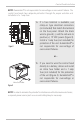
Control Head Installation POSITIVE NOTE: Humminbird® is not responsible for over-voltage or over-current failures. The control head must have adequate protection through the proper selection and installation of a 1 amp fuse. GROUND Figure 3 1a. If a fuse terminal is available, use crimp-on type electrical connectors (not included) that match the terminal on the fuse panel. Attach the black wire to ground (-), and the red wire to positive (+) 12 VDC power (Figure 3).
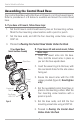
Control Head Installation Assembling the Control Head Base Your control head base will either have a tilt mount or a tilt and swivel mount. Refer to procedures A or B below to assemble and mount the control head base. A. If you have a tilt mount, follow these steps: 1. Set the tilt mount control head base in place on the mounting surface. Mark the four mounting screw locations with a pencil or punch. 2. Set the base aside, and drill the four mounting screw holes using a 9/64" bit. 3.
Control Head Installation Routing the Control Head Cables Under the Deck Use the following steps to route the control head cables under the deck. NOTE: Under the deck cable routing is not always possible. If this is not an option, the cables should be routed and secured above deck. NOTE: See the installation section for your transducer type in order to plan the location of the transducer and cable route. Tilt Mount or Tilt and Swivel Mount Control Head Base Tilt Mount or Tilt and Swivel Mount: 1a.
Control Head Installation Attaching the Control Head to the Base Follow these steps to attach the control head to the already-assembled base: NOTE: The transducer cable and power cable should be routed prior to securing the mounting bracket to the deck. 1. Apply marine-grade silicone sealant to the drilled holes for the mounting bracket. 2. Place the mounting bracket on the mounting surface, aligning with the drilled holes. 3.
Control Head Installation Attaching the Cables to the Control Head Follow these steps to attach the power and transducer cables to the control head: 1. Matching the cable plugs to the shape and orientation of the sockets, insert the transducer and power cables into the correct sockets on the control head (Figure 8). Power Temperature Transducer Figure 8 2.
Transducer Installation Overview Transducer Installation Overview The transducer can be installed on the transom of the boat, inside the hull, or onto a trolling motor, depending on your transducer type. The type of transducer you have will also determine how the cable will be routed. Go to the section that describes your transducer, and follow the steps to position and mount the transducer on your boat.
Transom Transducer Installation Transom Transducer Installation Locating the Transducer Mounting Position Turbulence: You must first determine the best location on the transom to install the transducer. It is very important to locate the transducer in an area that is relatively free of turbulent water.
Transom Transducer Installation • If the transom is behind the propeller(s), it may be impossible to find an area clear from turbulence, and a different mounting technique or transducer type should be considered, such as an Inside the Hull Transducer. • If you plan to trailer your boat, do not mount the transducer too close to trailer bunks or rollers to avoid moving or damaging the transducer during loading and unloading of the boat.
Transom Transducer Installation Preparing the Mounting Location Positioning the Mounting Bracket Level Level Figure 13 Boat Hull Types Require Different Mounting Positions After determining the mounting location for the transducer, follow the steps below to position and mount the transducer bracket. 1. Make sure that the boat is level on the trailer, both from port to starboard and from bow to stern, by placing your level on the deck of the boat, first in one direction, then in the other. 2.
Transom Transducer Installation 4. Make sure that the drill bit is perpendicular to the actual surface of the transom, NOT parallel to the ground, before you drill. Using a 5/32” bit, drill the two holes only to a depth of approximately 1”. NOTE: On fiberglass hulls, it is best to use progressively larger drill bits to reduce the chance of chipping or flaking the outer coating.
Transom Transducer Installation 2. Place the two ratchets, one on either side of the transducer knuckle, so that the beads on each ratchet line up with the desired position number on the knuckle (Figure 18a). If you are setting the ratchets at position 1, the beads on each ratchet will line up with the rib on the transducer knuckle to form one continuous line on the assembly (Figure 18b).
Transom Transducer Installation Inserting the Pivot Bolt Figure 19 Mounting the Assembly to the Transom Figure 20 3. Put the pivot bolt through the assembly to hold it in position and loosely install the nut, but do NOT tighten the nut at this time (Figure 19). 4. Align the mounting bracket transducer assembly with the drilled holes in the transom. With a 5/16" socket driver, mount the assembly to the transom using the two #10 - 1" long screws provided (Figure 20).
Transom Transducer Installation 6. Adjust the transducer assembly vertically, until the seam on the leading edge of the transducer (the edge closest to the transom of the boat) is level and just slightly below the hull (Figure 23). Adjusting the Transducer Mounting Position NOTE: The transducer has a natural downward slant of 4-5 degrees from leading edge (closest to the boat transom) to trailing edge (farthest away from the boat).
Transom Transducer Installation Routing the Cable The transducer cable has a low profile connector, which must be routed to the point where the control head is mounted. There are several ways to route the transducer cable to the area where the control head is installed. The most common procedure routes the cable through the transom into the boat. NOTE: Your boat may have a pre-existing wiring channel or conduit that you can use for the transducer cable. 1.
Transom Transducer Installation Routing the Cable 3. Place the escutcheon plate over the cable hole and use it as a guide to mark the two escutcheon plate mounting holes. Remove the plate, drill two 9/64" diameter x 5/8" deep holes, and then fill both holes with marine-grade silicone sealant. Place the escutcheon plate over the cable hole and attach with two #8 x 5/8" wood screws. Hand tighten only! 4.
Transom Transducer Installation Test and Finish the Installation Once you have installed both the control head and the transom transducer, and have routed all the cables, you must perform a final test before locking the transducer in place. Testing should be performed with the boat in the water. 1. Press POWER once to turn the control head on. If the unit does not power up, make sure that the connector is fully plugged into the terminal slot and that power is available. 2.
Transom Transducer Installation NOTE: It is often necessary to make several incremental transducer adjustments before optimum high speed performance is achieved. Due to the wide variety of boat hulls, however, it is not always possible to obtain high speed depth readings. 6. Once you have reached a consistently good sonar signal at the desired speeds, you are ready to lock down the transducer settings.
Inside the Hull Transducer Installation Inside the Hull Transducer Installation In-hull mounting generally produces good results in single thickness fiberglasshulled boats. Humminbird® cannot guarantee depth performance when transmitting and receiving through the hull of the boat, since some signal loss occurs. The amount of loss depends on hull construction and thickness, as well as the installation position and process. NOTE: In-hull mounting requires an installed and operational control head.
Inside the Hull Transducer Installation Determine the Transducer Mounting Location Decide where to install the transducer on the inside of the hull. Consider the following to find the best location: • Observe the outside of the boat hull to find the areas that are mostly free from turbulent water. Avoid ribs, strakes and other protrusions, as these create turbulence (Figure 28).
Inside the Hull Transducer Installation Trial Installation You will not be able to adjust the mounting after an inside the hull transducer is installed. It is best, therefore, to perform a trial installation first that includes running the boat at various speeds, in order to determine the best mounting area before permanently mounting the transducer. 1. Plug the transducer into the control head, then power up the control head.
Inside the Hull Transducer Installation Route the Cable 1. Once the mounting location is determined and you have marked the position of the transducer, route the cable from the transducer to the control head. Permanently Mount the Transducer 1. Make sure the position of the transducer is marked. 2. You may have to disconnect the cable to the control head and reconnect it at the end of this procedure. 3. Remove the water from inside the hull and thoroughly dry the mounting surface.
Trolling Motor Transducer Installation Trolling Motor Transducer Installation Several styles of the transducer are compatible with trolling motor mounting. (Figure 32). If you have a trolling motor bracket, refer to the separate installation instructions that are included with the bracket. Figure 32 You may purchase a Trolling Motor Adapter kit that will allow you to mount the transducer on the trolling motor.
Powering ON and OFF Press and hold the POWER-MENU key until the PiranhaMAX™ powers on, then release the key. To power off, press and hold the POWER-MENU key until the unit shuts down. When the PiranhaMAX™ powers on, the Start-Up menu temporarily appears. From this menu, select either Start-Up, Simulator, or SetUp. • Use Start-Up for on the water use. • Use Simulator for learning how to use the system with simulated sonar data; access Simulator by pressing the Right Arrow Key once.
What You See On the Display The PiranhaMAX™ displays underwater information in an easy-to-understand format. The top of the display corresponds to the water surface at the transducer, and the bottom of the display corresponds to the Depth Range automatically selected for the current water depth. The Bottom Contour varies as the depth under the boat changes. Digital readouts provide precise information for depth, fish and water temperature.
PMAX150/190c (Single Beam) and PMAX160/170 (Dual Beam) Display 2 1 3 4 5 7 6 9 8 10 * Units with 83 kHz Dual Beam sonar show targets in the wide beam as hollow fish icons.
PiranhaMAX™ Sonar Technology The PiranhaMAX™ is the easiest to use fishfinder ever. For most anglers, all you’ll ever need to do is power on and fish! The PiranhaMAX™ automatically determines depth and makes adjustments to keep the bottom and fish visible on the display. The PiranhaMAX™ uses sonar technology to send sound waves from the transducer into the water.
Single Beam Sonar The PiranhaMAX™150 and PiranhaMAX™190c use a 200 kHz single beam sonar system with a 20° area of coverage. Boat speed, wave action, bottom hardness, water conditions and transducer installation can all affect depth capability. Dual Beam Sonar The PiranhaMAX™160 and PiranhaMAX™170 use a 200/83 kHz dual beam sonar system with a wide (60°) area of coverage.
The Menu System A simple menu system allows you to access your PiranhaMAX™ adjustable settings. To activate the menu system, press the POWER-MENU key. Press the POWER-MENU key repeatedly to display the PiranhaMAX™ menu settings, one at a time. When a menu setting is on the display, use the RIGHT and LEFT Arrow keys to adjust the menu setting. Menus settings are saved and removed from the screen automatically after several seconds.
Depth Range (Setting Not Saved in Memory) Press the POWER-MENU key until DEPTH RANGE appears. Automatic is the default setting. When in automatic, the lower range will be adjusted by the unit to follow the bottom. (Auto, 15 to 600 ft [PiranhaMAX™150/160], 15 to 800 ft [PiranhaMAX™170/180/190c], Default = Auto) NOTE: In manual operation, if the depth is greater than the depth range setting, the bottom will not be visible on the display. Select AUTO to return to automatic operation.
Chart Speed (Setting Saved in Memory) Press the POWER-MENU key until CHART SPEED appears. Select a setting from 1-5 to increase or decrease the chart speed, where 1 is the slowest and 5 is the fastest chart speed. Chart speed determines the speed at which the sonar information moves across the display, and consequently the amount of detail shown. A faster speed shows more information and is preferred by most anglers; however, the sonar information moves across the display quickly.
Filter (Setting Saved in Memory) Press the POWER-MENU key until FILTER appears. Select either Off or On. Filter adjusts the sonar filter to limit interference on the display from sources such as your boat engine, turbulence, or other sonar devices. (On, Off, Default = Off) SetUp Menu (Setting Not Saved in Memory) Press the POWER-MENU key until SetUp appears. Press the RIGHT Arrow key to select On.
Fish ID+TM (SetUp Menu) (Setting Saved in Memory) Make sure that the SetUp menu is selected, then press the POWER-MENU key until FISH ID+TM appears. Select either Off to view “raw” sonar returns or On to view Fish symbols. Fish ID+TM uses advanced signal processing to interpret sonar returns, and will display a Fish Symbol when very selective requirements are met. A select number of possible fish returns will be displayed with their associated depth.
Structure ID® represents weak returns as light pixels and strong returns as dark pixels. This has the benefit of ensuring that strong returns will be clearly visible on the display. Black (Bottom Black) displays all pixels below the bottom contour as black, regardless of signal strength. This has the benefit of providing a high contrast between the bottom and other sonar returns on the display. NOTE: Bottom Black View is not available on color models.
Battery Alarm (SetUp Menu) (Setting Saved in Memory) Make sure that the SetUp menu is selected, then press the POWER-MENU key until BATTERY ALARM appears. Select Off or 8.5 to 13.5 Volts. Battery Alarm sounds when the input battery voltage is equal to or less than the menu setting. (Off, 8.5 to 13.5 Volts, Default = Off) Scroll through all SetUp menu choices to exit the SetUp menu.
Maintenance Your PiranhaMAX™ is designed to provide years of trouble-free operation with virtually no maintenance. Follow these simple procedures to ensure your PiranhaMAX™ continues to deliver top performance. If the unit comes into contact with salt spray, wipe the affected surfaces with a cloth dampened in fresh water. Do not use a chemical glass cleaner on the lens - this may cause cracking in the lens. When cleaning the LCD protective lens, use a chamois and non-abrasive, mild cleaner.
Troubleshooting Do not attempt to repair the PiranhaMAX™ yourself. There are no user-serviceable parts inside, and special tools and techniques are required for assembly to ensure the waterproof integrity of the housing. Repairs should be performed only by authorized Humminbird technicians. Many requests for repair received by Humminbird® involve units that do not actually need repair. These units are returned “no problem found.
3. There is no bottom reading visible on the display. If the loss of bottom information occurs only at high boat speeds, the transducer needs adjusting – see your PiranhaMAX™ Installation Guide for details. Also, in very deep water, it may be necessary to increase the sensitivity setting manually to maintain a graphic depiction of the bottom.
7. My unit loses power at high speeds. Your PiranhaMAX™ has over-voltage protection that turns the unit off when input voltage exceeds 20 VDC. Some outboard motors do not effectively regulate the power output of the engine’s alternator and can produce voltage in excess of 20 Volts when running at high RPMs. 8. The display begins to fade out. Images are not as sharp as normal. Check the input voltage. The PiranhaMAX™ will not operate on input voltages below 10 VDC. 9.
International Purchases A separate warranty is provided by international distributors for units purchased outside the United States. This warranty is included by your local distributor and this distributor maintains local service for your unit. Warranties are only valid in the area of intended distribution. Units purchased in the United States or Canada must be returned to our factory in the United States for service.
Humminbird® 1-Year Limited Warranty We warrant the original retail purchaser that products made by Humminbird® have been manufactured free from defects in materials and workmanship. This warranty is effective for one year from the date of original retail purchase. Humminbird® products found to be defective and covered by this warranty will be replaced or repaired free of charge at Humminbird’s option and returned to the customer freight prepaid.
Humminbird® Service Policy Even though you'll probably never need to take advantage of our incredible service policy, it's good to know that we back our products this confidently. We do it because you deserve the best. We will make every effort to repair your unit within three business days from the receipt of your unit at our factory. This does not include shipping time to and from our factory.
Returning Your Unit for Service Before sending your unit in for repair, please contact the factory, either by phone or by email, to obtain a Repair Authorization Number for your unit. NOTE: Please do not return your Humminbird® to the store for service. Please have your product model name and serial number available before calling the factory.
Specifications Depth Capability............................................................ 600 ft (185 m) – (PMAX150/160) 800 ft (250 m) – (PMAX170/180/190c) Power Output .................................................................800 Watts (PTP) – (PMAX150/160) 1600 Watts (PTP) – (PMAX170/180/190c) Operating Frequency.............................................
Contact Humminbird® Contact the Humminbird® Customer Resource Center in any of the following ways: By Telephone (Monday - Friday 8:00 a.m. to 4:30 p.m. Central Standard Time): 1-800-633-1468 By e-mail (typically we respond to your e-mail within three business days): cservice@johnsonoutdoors.