SCP 110 Course Computer Installation Guide 531913-2_A A
Thank You! Thank you for choosing Humminbird®, the #1 name in Fishfinders. Humminbird® has built its reputation by designing and manufacturing top-quality, thoroughly reliable marine equipment. Your Humminbird® accessory is designed for trouble-free use in even the harshest marine environment.
ENVIRONMENTAL COMPLIANCE STATEMENT: It is the intention of Johnson Outdoors Marine Electronics, Inc. to be a responsible corporate citizen, operating in compliance with known and applicable environmental regulations, and a good neighbor in the communities where we make or sell our products. WEEE DIRECTIVE: EU Directive 2002/96/EC “Waste of Electrical and Electronic Equipment Directive (WEEE)” impacts most distributors, sellers, and manufacturers of consumer electronics in the European Union.
Table of Contents Installation Overview 1 SCP110 Course Computer . . . . . . . . . . . . . . . . . . . . . . . . . . . . . . . . . . . . . . . . . . . . . . . . . . . . . . . . . . 3 Main Power . . . . . . . . . . . . . . . . . . . . . . . . . . . . . . . . . . . . . . . . . . . . . . . . . . . . . . . . . . . . . . . . . . . . . . 6 SC110 Control Head . . . . . . . . . . . . . . . . . . . . . . . . . . . . . . . . . . . . . . . . . . . . . . . . . . . . . . . . . . . . . . . .7 FXC110 Fluxgate Compass .
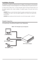
Installation Overview The autopilot is powerful and sophisticated but its reliability strictly depends on the meticulous installation and proper software configuration of all connected devices and optional accessories. For safety reasons, the best way is to section the power supply of the Course Computer (and so of the whole autopilot) with a switch installed in the electric panel of the vessel, only for this purpose.
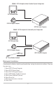
700048-1 SC110 Autopilot without Feedback System Configuration SC110 Control Head FXC110 Fluxgate Compass SCP110 Course Computer 700049-1 SC110 Autopilot for Outboard System Configuration SC110 Control Head FXC110 Fluxgate Compass SCP110 Course Computer Linear Rudder Feedback Mechanical Installation A mechanical installation should be performed before starting the electrical installation. These are the main steps: 1. Mount SCP110 Course Computer 2. Mount SC110 Control Head 3.
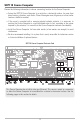
SCP110 Course Computer Review the following information to choose a mounting location for the Course Computer: • Fasten the SCP110 Course Computer to a vertical or a horizontal surface, far away from direct heating, vibrations, and shocks. Places like engine-room, bilge area, or other similar locations should be avoided. • If the vessel is provided with a reversing electro-hydraulic actuator, it is necessary to position the Course Computer in a well-ventilated room.
Vertical Mount: The default configuration is for a vertical Course Computer mount as shown below: SCP110 Vertical Mounting MAX 10˚ 10˚ OR Gyronav Wiring Gyronav Mounting TB23 Gyronav PIN #1 In a vertical mounting, the Course Computer is oriented horizontally on a vertical surface such as the bulkhead. Mount the Course Computer on a stable, flat surface. The removable cover must be secured and face out. The cables must hang down. Confirm that the box is level horizontally.
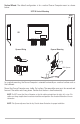
Horizontal Mount: If you need to install the SCP110 Course Computer horizontally, you must change the connector and the mounting as shown below: SCP110 Horizontal Mounting OR 10˚ 10˚ MAX Gyronav Wiring Gyronav Mounting TB23 Gyronav PIN #1 In a horizontal mounting, the Course Computer is mounted on a flat, horizontal surface such as the deck. Mount the Course Computer on a stable, flat surface. The removable cover must be secured and face up.
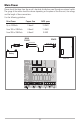
Main Power Power should be taken from the vessel’s electrical distribution panel through an external switch. The gauge of the cables should be chosen depending on the power of the drive unit, the voltage, and the length of these connections. Use the following guidelines: Drive Power Copper Area AWG specs Up to 100Watts 2.5mm2 13 AWG From 100 to 200Watts 4.0mm2 11 AWG From 200 to 350Watts 6.
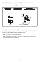
SC110 Control Head This is the “cockpit” of the autopilot, and it is through this unit that the user instructs the system about the operations that should be executed. See the SC110 Installation and Operations Manual for instructions and guidelines for mounting the control head. Install the Control Head on the main deck, in a position where it will be easily reached and controlled: carefully chose the proper location and orientation so that the display will be perfectly readable from the operating position.
FXC110 Fluxgate Compass This sensor is a key device of the autopilot. In fact, it is based on the electronic compass bearing that the autopilot keeps the vessel on the planned course, applying any needed correction, bringing you to the expected destination. An improper installation of this device will negatively affect the performance of the whole navigation system. The FXC110 Fluxgate Compass can be used with wood, fiberglass, and aluminum vessels.
FB30 Rudder Feedback The FB30 Rudder Feedback could be present or not, depending on the product. This is another key element of the autopilot. It is mechanically linked to the section of the rudder, and it informs the system on its real position. It is important that it is installed on a firm, rigid support respecting precisely the suggested mounting scheme.
Linear Rudder Feedback The Linear Rudder Feedback could be present or not, depending on the product. This is another key element of the autopilot. It is mechanically linked to the outboard engine and it informs the system on its real position. It is important that it is installed following the detailed instructions supplied in the box. Since the Linear Rudder Feedback is not the default setting, you should enter the INSTALLATION MENU and set the FEEDBACK TYPE to LF n.
Optional Electro-Hydraulic Unit For a correct use of our autopilot and for best performance, use hydraulic units suitable to the vessel steering system. The flow-rate is the most important parameter when you choose a pump: it should be calculated to obtain a hard-over to hard-over time of about 12 seconds (±10/20%). This is the formula to be used: FLOW-RATE (liters/min.) = RAM-VOLUME (liters) x 5 FLOW-RATE (cc/min.) = RAM-VOLUME (cc.
Continuous Running (CR model with solenoid valves) Wiring MOTOR: CR. MOTOR faston connectors. SOLENOIDS: TB11 connector. Software Settings (SC110 Installation Mode) POWER STEERING TYPE function should be set to SOL. SOLENOIDS TB11 LEFT LEFT RIGHT RIGHT LEFT + LEFT – RIGHT + RIGHT – MOTOR MOTOR MOTOR + MOTOR – MOTOR Constant Running Pump CR. MOTOR SCP110 The gauge of the cables should be chosen depending on the power of the pack driven, the voltage, and the length of these connections.
Optional Linear Drive In some boats, the rudder could be moved using a linear drive. Normally, this is the case of the boats equipped with a mechanical steering system. A correct linear drive should move the rudder with an hard-over to hard-over time of about 12 seconds (±10/20%). Linear Drive (equipped with reversing motor) Wiring MOTOR: R. MOTOR faston connectors. CLUTCH: TB11 connector.
Optional Second SC110 Control Head An optional extra Control Head should be installed with the same cares adopted for the first one. Even if it is named Second Control head, it is identical to the main Control Head both physically and functionally. The optional second SC110 Control Head should be connected to the Course Computer using the supplied cable (490343-2) in the TB8 CONTROL UNIT 2 connector.
Optional TC110 Tiller Control An optional Tiller Control can be installed on the main deck, in a position where it will be easily reached and controlled. It must be flush mounted. The optional TC110 Tiller Control should be connected to the Control Head using the supplied cable (490365-1), ACCESSORY connector.
Optional Second TC110 Tiller Control The optional second TC110 Tiller Control should be connected to the Control Head number 2 using the supplied cable (490365-1), ACCESSORY connector.
Optional AR32, AR33, AR34 Rudder Indicator The optional AR32, AR33, AR34 Rudder Indicator should be connected to the Course Computer using the supplied standard cable, TB9 RUDDER INDICATOR 1 connector.
Optional Second AR32, AR33, AR34 Rudder Indicator The optional second AR32, AR33, AR34 Rudder Indicator should be connected to the Course Computer using the supplied standard cable, TB10 RUDDER INDICATOR 2 connector.
Optional Chartplotter An optional Chartplotter/Multi-Function Display can be connected to the autopilot through the NAV1 input port. This data line is a NMEA0183 input port. Be sure that the baud-rate is set to 4.800 and, at least, one of the following sentences is enabled: [APA] or [APB] or [BOD+RMB] or [BOD+XTE] or [BOD+XTR]. This instrument should be connected to the Course Computer using the supplied standard cable, TB1 NAV1 NMEA0183 INPUT connector.
Optional Second Chartplotter/Wind Sensor An optional second Chartplotter / Multi-Function Display / Wind Sensor can be connected to the autopilot through the NAV2 input port. This data line is a NMEA0183 input port. Be sure that the baud-rate is set to 4.800 and, at least, one of the following sentences is enabled: • Chartplotter: [APA] or [APB] or [BOD+RMB] or [BOD+XTE] or [BOD+XTR]. • Wind Sensor: [MWV] or [VWR] This input is normally set to receive data from a wind sensor.
Heading Output The heading data information can be shared with some external devices (radar, compass repeaters, satellite receivers and similar). This data is outputted through a NMEA0183 port at 4.800 baud, fixed. The sentences outputted are: • HDG (@10Hz), Heading, Deviation & Variation* • HDT (@10Hz), Heading, True* • HDM (@1Hz), Heading, Magnetic *HDG and HDT heading data incorporate the Magnetic Variation information from the GPS sensor (RMC sentence).
Commissioning Tests After the installation of all mechanical and electrical components of the autopilot, a first testing session should be executed when the vessel is still moored. In order to obtain the best performance of the system, it is necessary to carry out at least a trial at water.
FXC110 Fluxgate Compass When the autopilot is in STANDBY mode, the large display shows the reading of the electronic compass. Verify that there is no interference and the value indicated by the main compass of the vessel is almost the same. In case of a significant difference, try to change the position of the compass (if interfered) or turn it on its axle until the difference is cancelled.
Electro-Hydraulic and/or Linear Drive Unit When the vessel is still moored, turn manually the helm to the center. In AUTO mode, execute a course change of 10 / 20 degrees and check that the rudder moves in the correct direction and in an intermediate position (the movement should be proportioned to the change). NOTE: If the autopilot is configured to work without the feedback, you will see the rudder moving to the hard-over position. A “NO RUDDER” alarm will also be displayed.
SCP110 Course Computer Specifications Nominal Supply Voltage . . . . . . . . . . . . . . . . . . . . . . . . . . . . . . . . . . . . . . .12 to 24Vdc (-15% / +20%) Power Consumption . . . . . . . . . . . . . . . . . . . . . . . . . . . . . . . . . . . . . .4W to 8W, power pack excluded Continuous Power Pack Drive Continuous Running Motor: . . . . . . . . . . . . . . . . . . . . . . . . . . . . . . . . . . . . . . . . . . . . . . . . . . . . . .30A Reversing Motor: . . . . . . . . . . . . . . . . . . . . . .
Sentences Handling This is a simple table that shows you how this information is handled depending on the operating mode of the autopilot: Input (TB1 connector) Function Needed Sentences MULTISENSOR RMC or VTG STANDBY None AUTO None AUTOTRACK GGA or GLL or RMC NAV APA or APB or BOD+RMB or BOD+XTE or BOD+XTR WIND MWV or VWR SOG visualization RMC or VTG COG visualization RMC or VTG Output (TB2 connector, Course Computer) Function Outputted Sentences Heading Output HDG (@10Hz) + HDT (@10Hz
27
Contact Humminbird® Contact the Humminbird® Customer Resource Center in any of the following ways: By Telephone: (Monday - Friday 8:00 a.m. to 4:30 p.m. Central Standard Time): 1-800-633-1468 By e-mail: (typically we respond to your e-mail within three business days): service@humminbird.