
User's Manual
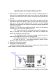

ID as ID32, then we need short the pin 8 and pin 2.
5. Push Button switch for output: this switch is just used on the slave
device, for a switch signal which can trigger other device as our
Media players, Audio box and etc.
6. LED Indicator for Slave device: When the module is setting for
slave, this LEDs indicator will be off in standby, if Slave device N
receive a command from the Host device, LED Indicator N will be
on for 1second and PB switch for output will trigger as a push
button function.
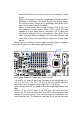
7. The host device can communicate with other device through UART
protocol:
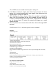
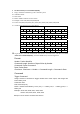
UART Protocol V3.2(Add descriptions for the command)
Interface
UART 9600bps 8N1
Command Length: Number of bytes follow by Header
Command: Packet Command
Data: Packet Data Checksum:
Checksum=Header+Command Length+Command+Data
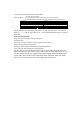
Command
Trigger Command
Active Slave Command (0x01)
Usage: Send this command to trigger related slave active ouput, and Dongle will return battery
level
Command: 0x01
Data: Slave ID (0-15)
Return: Related Slave Battery Level (0-2). 0=battery low, 1=battery good, 2=battery full
Example: send: 0xf5,0x04,0x01,0x00,0xFA
return: 0xf5,0x04,0x01,0x02,0xFC
Get Active Slave Command (0x02)
Usage: Get active wireless slave
Command: 0x02
Return: 32bits to indicate 32slave status
Example: send: 0xf5,0x04,0x02,0x00,0xFB