
User Guide


10
10
INSTALLATION
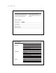
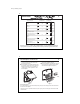
Table A
NOTE:
Do not connect a “Common” wire (sometimes labeled “C”) to any terminal on this thermostat.
Tape up the wire and do not use. This wire provides electricity to non-battery powered thermostats.
R
H
G
RC
W/B
Y
/O
Y1
RH, R, VR or 4
24 Volt
RC, VC
24 Volt Cool
G or F
Fan
Y, C or M
Air Conditioning Compressor
- or -
O
Reversing Valve operating in Cool mode.
(Single Stage Heat Pumps ONLY.)
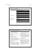
If the code letter on your
existing thermostat is
then mark the wire
with label shown
and connect to thermostat
terminal shown
W or H
Heating
- or -
B
Reversing Valve operating in Heat mode.
(Single Stage Heat Pumps ONLY.)
Y1
Heat Pump compressor
(Single Stage Heat Pumps ONLY.)
x
RH
x
RC
x
G
x
Y/ O
x
W/ B
x
Y1
41644_model44360_web.pmd
11
11
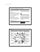
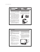
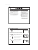
Mount Wallplate and Thermostat
■ Remove the wallplate from your thermostat by
pressing the release tab on the bottom of the
thermostat. (See Figure 2.)
■ Position wallplate on wall and pull existing wires
through large opening. Then level for appearance.
Mark holes for plastic anchors provided if your
existing holes do not line up with those on the
Hunter wallplate.
■ Drill holes with 3/16” bit and gently tap anchors
into the holes until flush with wall.
■ Reposition wallplate to wall, pulling wires through
large opening. Insert mounting screws provided
into wall anchor and tighten. (See Figure 3.)
Figure 2 Figure 3
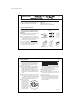
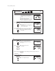
NOTE: 5-wire Systems
If your thermostat has one wire marked R or RH (4-wire system), then leave the jumper wire between the RH and
RC terminals on the wallplate.
Otherwise, if you have separate RH and RC wires (5-wire system), then remove the jumper wire between the RH
and RC terminals.
Y1
W/B
Y/O
Rh
Rc
G