TRAK I N S T A L L A T I O N M A N U A L
! B EF O R E YOU BE GIN SAFETY & PRECAUTIONS 3 FAN PLACEMENT 6 PRE-INSTALLATION 9 TOOLS NEEDED 10 IN THE BOX 11 INS TA L LAT IO N 1886 CONTENTS LEGACY The Hunter legacy is not only about quality—it’s about longevity. We invented the modern ceiling fan. We build fans that last, fans that are designed as fans.
! BE F OR E YO U B E G I N SAFETY & PRECAUTIONS Important Safety Information To prevent SERIOUS INJURY, DEATH and PROPERTY DAMAGE, you should read, understand and follow the warnings and instructions in this manual before installing or operating the fan. READ AND SAVE THESE INSTRUCTIONS. This manual must always be kept with the fan and should remain with the fan if it is transferred or sold. Always give manual to fan owner following installation. FIRE, ELECTRIC SHOCK and CRUSH HAZARDS.
! BE F OR E YO U B E G I N SAFETY & PRECAUTIONS Electric Shock Hazard To prevent serious injury or death: • BEFORE installing or servicing your fan, ALWAYS disconnect the power by turning off the circuit breaker or breakers, to the fan locations and confirm Lockout/Tagout procedures are in place. If you cannot lock the circuit breakers in the off position, securely fasten a prominent warning device, such as a tag, to the electrical panel.
! BE F OR E YO U B E G I N SAFETY & PRECAUTIONS CRUSH HAZARD To prevent serious injury or death, ALWAYS attach the Retention Cable to the fan motor and secure to the building structure on EVERY fan. The Retention Cable limits the distance the fan could fall in the unlikely event of mounting system failure. Failure to install and to secure the Retention Cable will void your warranty.
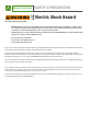
BE F ORE YO U B EG I N ! CHOOSE THE RIGHT LOCATION Check the room dimensions: Check the outlet box: 30 inches from blade tip to nearest wall or obstruction You must be able to secure the fan to building structure or fan-rated outlet box and clearly marked acceptable for fan support of 70 lbs (31.8 kg) or less.
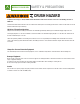
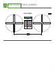
! BE F OR E YO U B E G I N FAN PLACEMENT FAN PLACEMENT A FAN SPACING CHART TRAK A B DIA MIN - MAX 8ft (96”) 20ft - 32ft 7ft (84”) 18ft - 28ft 6ft (72”) 16ft - 24ft 5ft (60”) 14ft - 20ft B 7
! BE F O R E YO U B E G I N FAN PLACEMENT ALWAYS mount fan so the bottom edge of blade to the floor is at least 10 feet. Always mount fans away from the following: Sprinkler Systems Prior to installing fans, review all codes applicable to sprinkler systems and fans to ensure code compliance and refer to NFPA 13: Fire Sprinkler System Installation. In any installation where fire sprinklers are present, the fan should not interfere with their operation.
! PRE-INSTALLATION CHECKLIST BE F OR E YO U B E G I N The location of the fan will alow for a minumum of 2 feet of blade clearance from any obstruction and at least 10 feet of clearance above the floor. If installing multiple fans, reference the fan placement chart for optimal spacing. The control panel voltage markings (either 100-120VAC or 220-240VAC) should match your building supply power. If you are unfamiliar with wiring, use a qualified electrician.
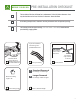
! TOOLS NEEDED BE F OR E YO U B E G I N Screwdrivers Ladder Included x2 10 1/2”/ M4 Wrench Right Angled Screwdriver Allen Wrench Blade Installation Tool
! BE F OR E YO U B E G I N IN THE BOX FAN COMPONENTS H I x4 E G J x12 x2 x2 F K M 1 L 2 E (1) Downrod F (1) Motor G (4) Blades H (1) Ceiling Bracket I (1) Canopy J (1) Motor Housing Cover K (K1)Data Cable Connector; (K2) Power Cable Connector L (1) Remote Control Assembly M Hanger Bracket Guide N (1) Installation Manual (not shown) 11
1 PREPARATION I N STA L L AT I O N A A F If you have a building management system you will need to set the dip switches for your fan IP address. Use the chart to set your switches. On is 1. 0 is the dip switch in the off position. 12 IP Bit 1 Bit 2 Bit 3 Bit 4 Bit 5 192.168.1.61 0 0 0 0 0 192.168.1.62 0 0 0 0 1 192.168.1.63 0 0 0 1 0 192.168.1.64 0 0 0 1 1 192.168.1.65 0 0 1 0 0 192.168.1.66 0 0 1 0 1 192.168.1.67 0 0 1 1 0 192.168.1.
INSTALLATION 2 CEILING BRACKET CRUSH HAZARD To prevent SERIOUS INJURY or DEATH, ALWAYS mount fan directly from building structure or outlet box marked acceptable for fan support of 70 lbs (31.8 kg). • • CAUTION: Do not install the fan from a single structure such as a purlin, truss, I-beam or bar joist. For any questions or concerns regarding the building structure, consult a structural engineer. A A Remove the four screws from the restraining bracket and set aside.
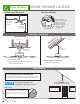
3 DOWNROD I NSTA L L AT I O N A B C D Place the preassembled downrod (E) through the canopy(I) and upper motor housing (J). Place the bottom of the downrod into the bracket of the fan while aligning the holes. Make sure power cable and communication cable are facing the power and data ports to ensure a connection.Place a bolt through each hole and secure each bolt with a nut. Connect the communication cable from the downrod to the fan. Connect the power cable from the downrod to the fan.
I N STA L L AT I O N 4 MOTOR ASSEMBLY CRUSH HAZARD. To prevent serious injury or death, ALWAYS attach the Retention Cable to the fan motor and secure to the building structure on EVERY fan. A B C D Lower the upper motor housing (J) and twist clockwise to secure. Ensure the fan is sealed by eliminating any gap between the housing and fan. Place hanger guide (M) through the back of the hanger bracket (H) until the back of the guide and bracket are flush.
5 RETENTION SYSTEM I N S TA L L AT I O N CRUSH HAZARD. To prevent serious injury or death, ALWAYS attach the Retention Cable to the fan motor and secure to the building structure on EVERY fan. A B Wrap retention cable around building structure that can withstand double the installed fan weight. Use mounting slot in the canopy to allow the retention cable to pass out of the canopy and through the gasket. Secure remaining cable to itself with cable clamps.
6 WIRING INSTALLATION Electric Shock Hazard Electric Shock Hazard. To prevent serious injury or death: • BEFORE installing or servicing your fan, ALWAYS disconnect the power by turning off the circuit breaker or breakers to the fan locations and confirm Lockout/Tagout procedures are in place. • If you cannot lock the circuit breakers in the off position, securely fasten a prominent warning device, such as a tag, to the electrical panel.
INSTALLATION 7 MOUNTING A Position data connector, power connector, and excess wiring inside the ceiling bracket. Lift the canopy and align the single ridge on the canopy with the single ridge on the ceiling gasket. Twist clockwise to secure. The singe ridge of the canopy will align with the two ridges of the ceiling gasket.
8 BLADES INSTALLATION A B C Match blade with colored circle to blade iron with the same colored circle. Slide blade over blade iron and align the blade screw holes with the blade iron holes. Place blade installation tool into hole closest to the fan to help align screw holes. Insert a screw into the remaining two screw holes. Tighten both screws Remove installation tool and insert a screw into the remaining screw hole and tighten. Repeat for each blade.
I NS TA L L AT I O N 9 REMOTE CONTROL A Press = Fan Off To access the battery compartment, remove the small Phillips head screw that secures the battery door to the transmitter assembly. The battery should be installed with the positive (+) side up. Replace with a CR2032 battery when necessary. The remote transmitter is already paired to the receiver and ready to use.
RE F E R EN C E MAINTENANCE Electric Shock Hazard Electric Shock Hazard To prevent serious injury or death: • BEFORE performing maintenance or service, ALWAYS disconnect the power by turning off the circuit breaker or breakers to the fan locations and confirm Lockout/Tagout procedures are in place. • If you cannot lock the circuit breakers in the off position, securely fasten a prominent warning device, such as a tag, to the electrical panel. • Do not remove covers while power is on.
TROUBLESHOOTING RE F E R EN C E Symptom FAN WILL NOT START Possible solution • Verify that the fan’s circuit breaker has power and that it is on. • Check for secured plug connections. Each connection should be checked to ensure they are fully engaged. • Inspect for loose wiring connections. Each termination should be checked to be sure they are firmly tightened. MOTOR IS PULLING EXESSIVELY HIGH AMPS • Make sure the motor voltage is a match for the supply voltage.