The Garden District Collection Bath Ventilator with Light English Página 21 Model 80705 48050-01 20131201 Español Owner’s Manual
! W A R N I N MAINTENANCE G The motor is permanently lubricated and never needs oiling. If the motor bearings are making excessive or unusual noises, replace the motor with the exact service motor. You should replace the impeller at the same time. TO REDUCE THE RISK OF FIRE, ELECTRIC SHOCK, OR INJURY TO PERSONS, OBSERVE THE FOLLOWING: 1. Use this unit only in a manner intended by the manufacturer. If you have questions, contact the manufacturer. 2.
x4 A * B * C x2 I Check all the parts. If damaged, call 1-888-880-3267 for replacements. Extra Screws 3/8” Cable Connector * NOTE: Strain relief cable connector must be installed. Not Included.
Before Installation NOTE: Remove all packing materials before installation. 1 2 I H Loosen screws. Turn off the power source. 3 4 I H E Remove the motor/blower from the housing. Remove packing material. 5 6 Remove the pre-loaded screw tip covers. Back out the pre-loaded screw tips until flush with the side of the housing.
7 8 Remove the wiring cover. Remove the wiring cover screw. 10 9 B Pop out the first wiring access slug. Use second if needed. Insert the strain relief into the housing and secure with the washer.
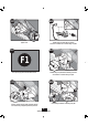
New construction attaching to joist A12 A11 5/8 1/2 Screw pre-loaded screws into joist or framing. Position the correct depth mark at the bottom edge of the joist based on the thickness of your sheetrock. A13 A14 F1 Pull wires through the strain relief. Go to step F1 on page 20 to connect the wires as shown. A16 0 A15 Install the wiring cover plate. Make sure all wiring connections are inside the box or under the wiring cover plate.
A17 A17 0 A18 Connect wiring from the motor to the wiring cover plate. 0 Reinstall the motor by inserting the tabs and pushing up into position. Make sure the wires are not pinched between the motor and the housing. A20 A19 Turn on the power source. Secure the motor by tightening the 2 screws. A21 A22 ON E1 OFF Test the motor. If the motor does not run, check the plug connection. Go to step E1 on page 18 to attach grill.
New construction suspended between joist B12 B11 5/8 1/2 5/8 1/2 Position the correct depth mark at the bottom edge of the joist based on the thickness of your sheetrock. Slide the mounting rails into brackets. B13 B14 1/8" Bit Drill a hole in the center of each outline. Mark position of screws by using holes as a template. B16 B15 Insert screws, leaving space between the screw head and the joist. Screws are not provided. Attach the rails onto the screws.
B17 B18 Tighten screws. Install the wiring cover plate. Make sure all wiring connections are inside the box or under the wiring cover plate. B20 B19 F1 Go to step F1 on page 20 to connect the wires as shown. Install the wiring cover plate. Make sure all wiring connections are inside the box or under the wiring cover plate.. B22 B21 Connect wiring from the motor to the wiring cover plate. Connect 4” duct and vent to the outside. Tape joints.
B23 B24 Secure the motor by tightening the 2 screws. Reinstall the motor by inserting the tabs and pushing up into position. Make sure the wires are not pinched between the motor and the housing. B25 B26 B26 ON OFF Test the motor. If the motor does not run, check the plug connection. Turn on the power source. B27 E1 Go to step E1 on page 18 to attach grill.
Existing construction accessible from above C11 EXISTING FAN NO EXISTING FAN OR Remove an existing fan and check to make sure the opening is large enough to accommodate the new motor housing (8”x 8.5”). Use the motor housing as a template to mark position. 8. 5 C12 Slide the mounting rails into brackets. Cut out an opening for the housing. C14 C13 5/8 1/2 5/8 1/2 Mark position of screws by using holes as a template.
C16 C15 1/8" Bit Drill a hole in the center of each outline. Insert screws, leaving space between the screw head and the joist. Screws are not provided. C18 C17 Attach the rails onto the screws. Tighten screws. C20 C19 Connect 4” duct and vent to the outside. Tape joints. If ducting does not fit securely, an adapter may need to be purchased. Pull wires through the strain relief.
C22 C21 F1 Go to step F1 on page 20 to connect the wires as shown. Tighten the strain relief screws. C24 C23 Install the wiring cover plate. Make sure all wiring connections are inside the box or under the wiring cover plate. Connect wiring from motor the motor to the wiring cover plate. C26 C25 Reinstall the motor by inserting the tabs and pushing up into position. Make sure the wires are not pinched between the motor and the housing. Secure the motor by tightening the 2 screws.
C28 C28 C27 ON Turn on the power source. OFF Test the motor. If the motor does not run, check the plug connection. C29 E1 Go to step E1 on page 18 to attach grill.
Existing construction accessible only from below D11 D12 EXISTING FAN Move the housing into position above the ceiling. Remove an existing fan and check to make sure the opening is large enough to accommodate the new motor housing (8”x 8.5”). D13 1 2 D14 Attach existing ducting to duct connector. Tape joints. If ducting does not fit securely, an adapter may need to be purchased. Pull wires through strain relief. D15 D16 F1 Go to step F1 on page 20 to connect the wires as shown.
D18 D17 Install the wiring cover plate. Connect wiring from the motor to the wiring cover plate. D19 D20 Secure the motor by tightening the 2 screws. Reinstall the motor by inserting the tabs and pushing up into position. Make sure the wires are not pinched between the motor and the housing. D21 D22 D22 ON OFF Test the motor. If the motor does not run, check the plug connection. Turn on the power source.
Attaching the grill NOTE: The grill’s size, shape, and number of lights may vary. E2 E1 Remove the two star nuts. Align posts B and D (stamped into motor housing) with posts B and D (stamped into light fixture). Slide support bar and hiding plate onto posts. E4 E3 [a] Feed the mounting cable through the hiding plate, then attach mounting cable [a] to the support bracket. Plug in wiring harness. E5 E6 Raise the bezel onto the threaded rod of the support bracket.
E8 E7 Unscrew glass retainer ring using the glass ring tool provided. Screw finial onto the threaded rod of the support bracket. E10 E9 Place the glass onto the sockets and re-install the glass retaining rings using the glass ring tool. Complete. Wiring the fan F1 Ground Black Green White A 2 Pin Bare Copper Black Main Switch 1 (AC In) Fan Motor F White White Light 3 Pin Black Light *Option Black *Option Fan & Main Light Together Connect wires as shown.
Trouble Shooting Problem: Fan does not come on. Solution: running, place your hand near the vents to feel the air movement. Problem: Light does not come on. Solution: Problem: Fan is noisy.
Warranty Hunter Home Comfort Bath Exhaust Fan LIMITED WARRANTY Hunter Home Comfort makes the following limited warranty to the original user or consumer purchaser of this Hunter bath exhaust fan: date of sale to you due to a defect in material or workmanship, we will repair or, at our option, replace the defective part free of charge for parts and labor performed at our nearest service center or at our Service Department in Marietta, Georgia.
The Garden District Collection Ventilador para baño con luz Español Manual del Propietario Modelo 80705 48050-02 20131201
ventilador, el motor/soplador y el interior del alojamiento. ! A D V E R T E N C I A PARA REDUCIR EL RIESGO DE INCENDIO, CHOQUE ELÉCTRICO O LESIONES A PERSONAS, OBSERVE LO SIGUIENTE: 1. Utilice esta unidad sólo de la manera indicada por el fabricante. Si tiene alguna pregunta, contacte con el fabricante. 2.
x4 A * B * C están dañados, llame al 1-888-880-3267 para obtener un reemplazo. x2 I Tornillos adicionales Conector de cable de 3/8” * NOTA: Debe estar instalado el manguito de alivio de tensión del cable. No incluido.
Antes de la instalación NOTA: Retire todo el material de embalaje antes de la instalación. 2 1 I H Apague la fuente de alimentación. Afloje los tornillos. 3 4 I H E Retire el material de embalaje. Retirer le moteur/souffleur du boîtier. 5 6 Retire las cubiertas de las puntas de tornillo precargadas. Retire las puntas de tornillo precargadas hasta que estén a nivel con el lado del alojamiento.
7 8 Retire el tornillo de la cubierta del cableado. Retire la cubierta del cableado. 10 9 B Inserte el manguito de alivio de tensión (no se incluye) en la caja y sujételo firmemente con una arandela. Retire el primer tapón metálico de acceso del cableado. Utilice el segundo si es necesario.
Construcción nueva fijación a la viga A12 A11 5/8 1/2 Ubique la correcta marca de profundidad en el borde inferior de la viga, según el espesor de su plancha de yeso. Instale los tornillos precargados en la viga o el marco. A13 A14 F1 Vaya al paso F1 en la página 20 para onnectoer les fils tel qu’indequé comme indiqué. Tienda los cables a través del manguito de alivio de tension. A16 0 A15 Instale la placa de cubierta del cableado.
A17 A17 0 A18 Conecte el mazo de cables. NO PERMITA QUE EL MOTOR/SOPLADOR CUELGUE DEL MAZO DE CABLES. 0 Vuelva a instalar el motor/soplador introduciendo las pestañas y levantando a su posición. Asegúrese que los alambres no se pellizquen entre el motorsoplador y el alojamiento. A20 A19 Asegure el motor/soplador apretando los 2 tornillos. Encienda la fuente de alimentación. A21 A22 Ence ndid o E1 Apag ado Vaya al paso E1 en la página 18 para fijar la rejilla. Pruebe el motor/soplador.
New construction suspended between joist B12 B11 5/8 1/2 5/8 1/2 Deslice los rieles de montaje en los soportes. Ubique la correcta marca de profundidad en el borde inferior de la viga, según el espesor de su plancha de yeso. B14 B13 1/8" Bit Marque la posición de los tornillos utilizando los agujeros como una plantilla. Marque la posición de los tornillos utilizando los agujeros como una plantilla. B16 B15 Fije los rieles con los tornillos.
B17 B18 Apriete los tornillos. Instale la placa de cubierta del cableado. Asegúrese que todas las conexiones de cableado estén dentro de la caja o debajo de la placa de cubierta del cableado. B19 B20 F1 Vaya al paso F1 en la página 20 para onnectoer les fils tel qu’indequé comme indiqué. Instale la placa de cubierta del cableado. Asegúrese que todas las conexiones de cableado estén dentro de la caja o debajo de la placa de cubierta del cableado. B21 B22 Conecte el mazo de cables.
B23 B24 Asegure el motor/soplador apretando los 2 tornillos. Vuelva a instalar el motor/soplador introduciendo las pestañas y levantando a su posición. Asegúrese que los alambres no se pellizquen entre el motor/soplador y el alojamiento. B25 B26 B26 Ence ndid o Apag ado Pruebe el motor/soplador. Si el motor/soplador no funciona, verifique la conexión del enchufe. Encienda la fuente de alimentación. B27 E1 Vaya al paso E1 en la página 18 para fijar la rejilla.
Construcción existente accesible desde arriba C11 VENTILADOR EXISTENTE SIN VENTILADOR EXISTENTE O Utilice el alojamiento del motor/soplador como una plantilla para marcar la posición. Retire el ventilador existente y asegúrese que la abertura sea suficientemente grande para acomodar el alojamiento del motor/soplador nuevo (8 pulg. x 8 1/2 pulg.). 8. 5 C12 Recorte una abertura para el alojamiento. Deslice los rieles de montaje en los soportes.
C16 C15 1/8" Bit Introduzca los tornillos, dejando espacio entre la cabeza del tornillo y la viga. No se proporcionan los tornillos. Taladre un agujero en el centro de cada perfil. C18 C17 Fije los rieles con los tornillos. Apriete los tornillos. C20 C19 Tienda los cables a través del manguito de alivio de tension. Conecte un ducto de 4” y ventile hacia el exterior. Aplique cinta a las uniones. Si el ducto no se ajusta firmemente, puede ser necesario comprar un adaptador.
C22 C21 F1 Vaya al paso F1 en la página 20 para onnectoer les fils tel qu’indequé comme indiqué. Apriete los tornillos del aliviador de tensiones. C24 C23 Instale la placa de cubierta del cableado. Asegúrese que todas las conexiones de cableado estén dentro de la caja o debajo de la placa de cubierta del cableado. Conecte el mazo de cables. NO PERMITA QUE EL MOTOR/ SOPLADOR CUELGUE DEL MAZO DE CABLES.
C28 C28 C27 Ence ndid o Apag ado Pruebe el motor/soplador. Si el motor/soplador no funciona, verifique la conexión del enchufe. Encienda la fuente de alimentación. C29 E1 Vaya al paso E1 en la página 18 para fijar la rejilla.
Construcción existente accesible sólo desde abajo D11 D12 EXISTING FAN Mueva el alojamiento a su posición encima del techo. Retire el ventilador existente y asegúrese que la abertura sea suficientemente grande para acomodar el alojamiento del motor/soplador nuevo (8 pulg. x 8 1/2 pulg.). D13 1 2 D14 Conecte el ducto existente con el conector de ducto. Aplique cinta a las uniones. Si el ducto no se ajusta firmemente, puede ser necesario comprar un adaptador.
D18 D17 Instale la placa de cubierta del cableado. Asegúrese que todas las conexiones de cableado estén dentro de la caja o debajo de la placa de cubierta del cableado. Conecte el mazo de cables. NO PERMITA QUE EL MOTOR/ SOPLADOR CUELGUE DEL MAZO DE CABLES. D19 D20 Vuelva a instalar el motor/soplador introduciendo las pestañas y levantando a su posición. Asegúrese que los alambres no se pellizquen entre el motor/soplador y el alojamiento. Asegure el motor/soplador apretando los 2 tornillos.
Fijar la rejilla NOTA: El tamaño, forma y color de los artefactos puede variar. E2 E1 Retire las dos tuercas de estrella. Alinee lospostesB y D (estampados en el alojamiento delmotor) con los postesB y D (estampados en el artefacto de iluminación). Deslice la barra de soporte y la placa encubridorahasta lospostes. E3 E4 [a] Conecte el manojo de alambres. Pase el cable de montaje de a través de la placa encubridora, luego fije el cable de montaje [a] en el soporte de apoyo.
E8 E7 Enrosque la cubierta ornamental en la varilla roscada del soporte de apoyo. Desenrosque el anillo de retención de la pantalla usando la herramienta para el anillo suministrada. E10 E9 Completo. Coloque la pantalla en los portalámparas y reinstale los anillos de retención de la pantalla usando la herramienta para el anillo.
Solución de problemas Problema: El ventilador no está operando. Solución: el ventilador esté funcionando, coloque su mano cerca de los conductos de ventilación para sentir el movimiento del aire. interruptor automático. cableado. Problema: La luz no funciona. Solución: interruptor automático. cableado. Problema: El ventilador hace ruido.
Garantía Hunter Home Comfort Extractor de aire para baño GARANTÍA LIMITADA Hunter Home Comfort establece la siguiente garantía limitada al usuario o comprador original de este Extractor de aire para baño Hunter: Si alguna pieza de su Extractor de aire para baño Hunter (con excepción de las lámparas de vidrio y las bombillas) falla en cualquier momento dentro de un año después de la fecha de compra debido a una falla de material o mano de obra, repararemos o, a nuestra elección, reemplazaremos la pieza defec