I n s t a l l a t i o n G u i d e ENGLISH See page 2 READ and SAVE THESE INSTRUCTIONS 42935-01 06/04/2007 Español Vea la página 19 Energy Star Bath Fan Models 82030, 82031, & 82032
W arning TO REDUCE THE RISK OF ELECTRIC SHOCK OR INJURY, OBSERVE THE FOLLOWING: 1) Read all instructions before attempting to install or use this appliance. This appliance is for general ventilating use only. Do not use this appliance for ventilating hazardous or explosive materials.
6) Never place a switch where it can be reached from a tub or shower. Do not install this appliance in a tub or shower enclosure. 7) Installation work and electrical wiring must be done by qualified person(s) in accordance with all applicable codes and standards, including fire-rated construction codes and standards. 8) When cutting or drilling into wall(s) or ceiling, do not damage electrical wiring or other hidden utilities. 9) Do not install this product in a wall.
F 95044-01-000 Mounting Rails Check all the parts. If damaged, call 1-888-830-1326 for replacement. G 97128-01-000 Housing x3 A H I * B 97517-01-000 03242-07-133 Wiring Cover Wiring Cover Screw 3/8” Cable Connector J *C K x2 D Attachment Screws x4 E L Mounting Screws x2 M * NOTE: Strain relief (not supplied) cable connector must be installed.
D C Remove the fan assembly from the housing. Loosen the wiring cover screw. E Remove the wiring cover. Choose Installation Option For New Construction - attaching to joist, go to step A1, page 5. For New Construction - suspended between, joists go to step B1, page 7. For Existing Construction - accessible from above, go to step C1, page 9. For Existing Construction - accessible only from below, go to step D1, page 12.
Section A - New Construction - attaching to joist A1 OR Pop out a wiring access slug. A3 A2 5/8 1/2 5/8 1/2 Position the correct depth mark at the bottom edge of the joist based upon the the thickness of your sheetrock. A4 Drive mounting screws (supplied) into joist or framing. A5 3” Run the power supply wire through the strain relief, leaving 3” between the end of the wire and the strain relief. Tighten the strain relief around the wire.
A6 Go to Section E Final Installation on page 14. Connect 4” duct and vent to the outside. Use duct tape to secure joints. If ducting does not fit securely, an adapter may need to be purchased. Section B - New Construction – suspended between joists B1 OR Pop out a wiring access slug. B2 B3 5/8 1/2 5/8 1/2 Position the correct depth mark at the bottom edge of the joist based upon the the thickness of your sheetrock. Slide the mounting rails into brackets.
B5 B4 1/16” bit Drill a pilot hole at the TOP of each outline. Mark position of screws by using holes as a template. B7 B6 Insert mounting screws, leaving space between the screw head and the joist. (Screws are supplied.) Attach the rails onto the screws. B8 B9 Tighten screws. 42935-01 06/04/2007 3” Run the power supply wire through the strain relief, leaving 3” between the end of the wire and the strain relief. Tighten the strain relief around the wire.
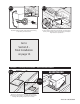
B10 B11 Connect 4” duct and vent to the outside. Use duct tape to secure joints. If ducting does not fit securely, an adapter may need to be purchased. Install the wiring and the strain relief into the wiring access hole you made earlier. Go to Section E Final Installation on page 14. Section C - Existing Construction – accessible from above C1 �⁄� OR 9 11” ” NO EXISTING FAN Remove an existing fan and check to make sure the opening is large enough to accommodate the new fan housing.
C2 OR Pop out a wiring access slug. C3 C4 5/8 1/2 Slide the mounting rails into brackets. Using the depth markings on the housing, position the bottom edge of the housing so that it will be flush with the sheetrock. C6 C5 Mark position of screws by using holes as a template. 42935-01 06/04/2007 5/8 1/2 Drill a pilot hole at the TOP of each outline, AS SHOWN.
C7 C8 Insert mounting screws, leaving space between the screw head and the joist. (Screws are supplied.) Attach the rails onto the screws. C9 C10 3” Run the power supply wire through the strain relief, leaving 3” between the end of the wire and the strain relief. Tighten the strain relief around the wire. Tighten screws. C11 C12 Install the wiring and the strain relief into the wiring access hole you made earlier. Connect 4” duct and vent to the outside. Use duct tape to secure joints.
Go to Section E Final Installation on page 14. Section D - Existing Construction – accessible from below D2 D1 Remove one of the wiring access slugs on the top of the housing. Use a second wiring access plug if needed. D3 Remove the mounting rail brackets. D4 EXISTING FAN Run the power supply wire through the strain relief, leaving 3” between the end of the wire and the strain relief. Tighten the strain relief around the wire.
D5 D6 Install the wiring and the strain relief into the wiring access hole you made earlier. Connect 4” duct and vent to the outside. Use duct tape to secure joints. If ducting does not fit securely, an adapter may need to be purchased. D7 D8 5/8 1/2 5/8 1/2 Position the bottom edge of the housing flush with the sheetrock. Move the housing into the ceiling. D9 Go to Section E Final Installation on page 14. Screw mounting screws into joist or framing.
Section E - Final Installation E1 E2 Ground Green A Bare Copper A A Black White Connect the wiring as shown. Install the wiring cover box. Make sure all wiring connections are inside the wiring cover box. NOTE: Though this final installation section shows the housing mounted to a joist, the final installation procedure is the same whether the housing is mounted to a joist or suspended between joists. E3 E4 Connect fan wiring harness. DO NOT ALLOW THE FAN TO HANG FROM THE WIRING HARNESS.
E7 E8 Install the bezel by inserting the wire clips into the tabs on the inside of the housing. Complete. E9 Restore power at the source.
Preventative Maintenance A clean fan provides better service. Disconnect the power supply and clean the fan as listed below. TO CLEAN THE BEZEL: Carefully pull the bezel down. Use water, a mild detergent such as dishwashing liquid, and a soft cloth to clean the bezel. DO NOT use abrasive cloths, steel wool pads, or scouring powders. Dry the bezel and reinstall it. TO CLEAN THE FAN ASSEMBLY: Disconnect power to the unit by switching off the breaker or removing the fuse. Turn the wall switch off.
Trouble Shooting (cont.) If you need parts or service assistance, please call 888-830-1326 or visit us at our website at http://www. hunterfan.com.
42935-01 06/04/2007 18