ACC2 BUILT TO COMMAND EVEN THE LARGEST PROJECTS Quick Start Guide
POWERFUL. INTELLIGENT. FLEXIBLE. THE ACC2 CONTROLLER DELIVERS ADVANCED WATER MANAGEMENT TO MEET THE DEMANDS OF LARGE-SCALE COMMERCIAL PROJECTS. Troubleshooting Need more helpful information on your product? Find tips on installation, controller programming and more. hunter.direct/acc2 2 1-800-733-2823 hunter.
TABLE OF CONTENTS Important Connections and Tips................... 4 Facepack................................................................ 4 Reversing the Facepack..................................... 4 Connecting and Disconnecting the Facepack..5 SyncPort™ Connection .......................................5 SD Card Reader....................................................5 Battery..................................................................5 Internal Features......................................
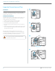
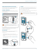
Important Connections and Tips Important Connections and Tips FACEPACK ① “Facepack” is a Hunter term for the enclosed, removable control panel and display assembly. It contains the brain and memory of the controller. REVERSING THE FACEPACK The ACC2 facepack and controls can be reversed in the door frame, so they can be operated with the door open while looking at the modules and wiring. 1. 2. 3. 4. Pull the facepack away from the face frame. The facepack is held in place by a magnet.
Important Connections and Tips CONNECTING AND DISCONNECTING THE FACEPACK The facepack cable connection is located just below the light on the Power Supply Board. Turn power to controller off before connecting or disconnecting the facepack. SYNCPORT™ CONNECTION The SyncPort connection is a proprietary Hunter connection for external interface devices. It is located near the top of the Power Supply Module.
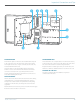
Important Connections and Tips INTERNAL FEATURES ① ② ③ ④ ⑤ ⑥ ⑦ ⑧ Facepack Cable Power Supply Board Earth Ground Lug Slide Locks Flow Expansion Module slot Wire Tie Holders Transformer Fuse Optional Wi-Fi or LAN slot FACEPACK CABLE The facepack cable connection is located beneath the status light. It is a standard connector with a locking lever on one side, which must be pressed in to remove the cable.
Important Connections and Tips ① ②③ ④ ④ ⑤ ⑥ ➑ ➐ FLOW EXPANSION A2C-F3 flow expansion modules add 3 additional flow inputs to the controller. These modules may only be added to the lower right module slot, one per controller, and it is the only module that will fit in this slot. The flow expansion module has DC voltage and polarity, and the + or red connection from the flow sensor must be connected correctly to the + (positive) terminals on the module.
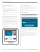
Operating the Controls Operating the Controls Attention Messages ACC2 has a simple control panel with unique operating features. A new controller installation will begin with at least one or two Attention messages, because the controller has experienced a “power outage” in shipping, and may be discovering new modules. This is normal. 1. The dial is used to rotate through selections and then pushed to select, or to enter information. 2. To the right of the LCD display are 4 “soft” keys.
Home and Activity Screens VIEW MESSAGES Home and Activity Screens A flashing alarm symbol at the bottom of the display indicates that something unusual has been detected. When the symbol is flashing, a soft key will link to View Messages. Press the key to view the most recent messages in the Attention screen. The Home screen offers basic information and soft key shortcuts to common functions.
Home and Activity Screens ACTIVITY SCREEN When the controller is running stations, the Home screen becomes the Activity screen, with additional information and functions. All running stations are displayed, along with the program that is running them, the mode in which they are running, and the amount of run time remaining on the station. Individual items may be selected directly from the Activity screen and stopped without affecting other irrigation. See Selective Stop section on page 14.
Basic Programming and Setup Basic Programming and Setup SETTINGS, TIME AND DATE From the Home screen, press Main Menu, and dial to Settings. NAMES ACC2 allows items to be named, with an on-screen keyboard that appears in the Name field (or from a mobile device, if the optional Wi-Fi module is installed). Names are useful in large systems, especially in the more advanced Flow Operations. Select Settings, and dial to Regional Settings. Choose language, time and date formats, and units of measurement.
Basic Programming and Setup PUMP/MASTER VALVE SETUP From Main Menu, dial to the Stations menu. Set Station P/MV Usage for each station, if necessary. P/MV outputs 1 through 3 always refer to the output terminals on the Power Supply Board. P/MV outputs 4, 5, and 6 can be assigned to regular station outputs. See Soft P/MVs on page 12. SOFT P/MVS (4-6) P/MV outputs 4 through 6 will show as “Disabled”, unless you select one of the station outputs to be used as an additional P/MV.
Basic Programming and Setup MANUAL STARTS AND TEST STOP COMMANDS On the Home screen, the Manual soft key lets you start stations, programs, or a test program. Once you press Manual, there are three choices: Any running irrigation can be stopped immediately from the Home screen. The top soft key offers the following choices for stopping irrigation: MANUAL STATIONS Specify one or more stations to run and enter a run time for them.
Basic Programming and Setup STOP COMMANDS (CONTINUED) SELECTIVE STOP You can also use the dial to scroll through the list of running stations and programs on the Home screen and click to stop any one of them instead of the entire list. If you highlight an active station, the Stop button will allow you to Stop Station, or Stop Program. Stop Program will stop the entire program that caused the station to run, but allows other programs to keep running.
Basic Programming and Setup INTELLIGENT CURRENT SENSING ACC2 has no artificial programming limits preventing overlapping programs and stations. The controller senses how much electrical current is being drawn, and will suspend stations automatically if the combined current threatens the transformer. It is also possible to set controller and station limits (Stations, Station Limits) to control how many outputs may operate at once.
Basic Programming and Setup WATER DAYS Verify you are in the correct program by number or name, and set the days for automatic watering. SEASONAL ADJUST Programs menu, Seasonal Adjust. When using Solar Sync, set up at Devices page first, then go to Seasonal Adjust. Mode selects a type of schedule. • Day of Week: Check the boxes for the days the program should water. • Odd/Even: Water only on odd or even calendar dates, to comply with water restrictions.
Basic Programming and Setup PROGRAM RULES Program Rules customizes each program for special purposes. PROGRAM SUMMARY Once a program has start times, run times, and water days, it will run automatically without further setup. To see how the program is configured, select Program Summary from the Programming screen. IGNORE CALENDAR DAYS OFF Check the box if the program should be allowed to run on Calendar Days Off that apply to other programs.
Basic Programming and Setup P/MV OPERATION (PUMP/MASTER VALVE OPERATION) Dial to the Devices menu, and select P/MV Operation. Each P/MV will be checked for Normally Closed operation. This is a station level setting, meaning that the P/MV is activated by stations when they begin to run. The Station Setup menu allows you to set each station for the P/MV outputs it needs to run water. SENSORS Rain shutoff and other sensors must be setup in the Devices menu.
Basic Programming and Setup SENSOR RESPONSE Located on the Devices menu, Sensor Response sets which sensors will shut off which programs in basic operations. The sensor responses are set up for each program, one page at a time. If you want the same responses for multiple programs, set up the responses for the first program, then click the Copy soft key. You can then change the program number and click the Paste soft key to duplicate the settings.
Basic Programming and Setup SOLAR SYNC After connecting a Solar Sync sensor to the controller, set up operation in the Devices, Solar Sync menu. FLOW SENSORS After connecting one or more flow sensors to the controller, set up operation in the Devices, Flow Sensors menu. • Check the box to Enable Solar Sync. • Choose the Region and set the Water Adjustment, according to the Solar Sync manual instructions. • For normal operations, this is all that is necessary.
Stations Menu Stations Menu STATION SETUP Allows stations to be named. Most other functions are described in more detail in the Flow Operations section. Pulse type: enter the amount equal to a single pulse. Enter the information for each flow sensor that is connected to a flow terminal. There are copy and paste soft keys available, if all the meters are the same type and size. Once this information is entered for each flow sensor input, the controller is ready to read flow.
Basic Programming and Setup CYCLE & SOAK BLOCKS Used to control runoff and puddles when soil or slope cannot absorb all irrigation at once. A Block is an electronic group of stations that runs at the same time, for the same run time, within a program (Blocks replace “SSGs” in original ACC). Set the Cycle to the maximum time the station can run at once, before runoff occurs. Set the Soak to the minimum time the station must wait before applying another cycle.
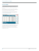
Stations Menu STATION LIMITS STATION SUMMARY Station Limits set how many stations can run at once. The Station Summary is a report available for each station showing exactly how it is going to run, based on the current setup and programming. It is a report only, and does not allow changes to be made directly from this screen. Stack or Overlap means that each program can be manually set to overlap with other programs, or be required to stack. Programs that are set to stack can only run by themselves.
Devices Menu Devices Menu CLIK SENSORS Devices allows setup of common external devices that the controller can use. The functions in the Devices menu are covered in more detail in other sections. Clik sensor setup is covered in detail in the Basic Programming, Sensors, and Clik Sensors section on page 18. SENSOR RESPONSE Sensor Response is covered in detail in the Basic Programming, Sensors, and Flow Sensors section on page 20.
Flow Menu Flow Menu Settings Menu The flow menu includes all setup for the various flow functions. These are described in detail in the Flow Operations section on page 32. TIME/DATE CLEAR FLOW ALARMS The Clear Flow Alarm function enables a MainSafe or Flow Zone that has had an Overflow alarm to water again. If a Flow Zone or MainSafe flow alarm has occurred, a shortcut key is provided on the Home screen to Clear Flow Alarms. Sets time and date, see Basic Programming, and Time/Date section on page 25.
Settings Menu USER MANAGEMENT This allows a password to be created for the controller. Users will be required to enter the correct PIN (personal identification number) before operating the controller. If a single PIN is entered at the top, it is required for all users, and provides the same level of access to all. There are two levels of authorization, Admin and Crew. Crew level access allows manual operations and the ability to view programming. Only Admins may modify programming and other settings.
Diagnostics Menu Diagnostics Menu VIEW LOGS There are 3 types of logs, and a filter function to narrow the number of logs displayed. ALARM LOGS The controller will store up to 250 alarm logs, with date and time, beginning with the most recent alarm. Use the dial to advance forward and backward through the alarm list. Attention messages do not interfere with normal automatic irrigation. All attention messages on the Home screen create logs.
Diagnostics Menu STATION LOGS Station logs record every single event that occurs in the controller (up to 1500 events), beginning with the most recent. This can be useful for advanced troubleshooting, or to verify that a station actually watered. FILTER LOGS This allows any of the three logs to be filtered by date, or by record number. EXPORT LOGS All logs can be written to the SD card, described in the Advanced Features section. Advanced Features section on page 30.
Diagnostics Menu STATION-P/MV DIAGNOSTICS Shows the electrical current draw in milliamps for all active stations and P/MV outputs. SOLAR SYNC DIAGNOSTICS Shows the last time the Solar Sync sensor communicated, and the current state of its alarm sensors (Rain and Freeze). This soft key is only shown if Solar Sync has been set up in the Devices menu. The Test Connection soft key checks for the presence of a wired sensor, or for the presence of the receiver for a wireless sensor.
Advanced Features Advanced Features EASY RETRIEVE Saves the current controller setup, so that it may be restored to this point at a future date. EXPORT LOGS Logs may be exported in a simple text format to the internal SD card in the facepack if additional help is needed for troubleshooting, or just for record-keeping purposes. Enter a unique file name by clicking in the File Name box. Select the boxes for the types of logs desired. Select and click the Export Logs button to save the file to the SD card.
Advanced Features RESET MEMORY FIRMWARE UPDATE Sometimes it is preferable to simply erase the controller, to begin again from a clean start. There are several reset options. ACC2 can be updated whenever a new version of the operating system or any of the internal modules is released. These updates are usually available from www. hunterindustries.com, or are sent via email. It is always advisable to stay current with controller updates.
Flow Operations Flow Operations FLOW MANAGER The two major parts of Flow Operations are the Flow Manager, and the Flow Monitor. Flow Manager uses station flow information to run simultaneous stations to reach a flow rate target that is specified by the user. It will turn on as many stations as it can to stay at or near the flow target until there are no more stations to run. This does not require a flow sensor input. Checking either will display a reminder of the steps for setting these features up.
Flow Operations SET UP FLOW MONITOR The Flow Monitor requires the following information to operate correctly: • Install and set up a flow sensor (Devices menu). • Install and set up a P/MV (Devices menu). • Set up a Flow Zone, and complete all information for the Flow Zone (Flow menu). • Attach each station to a Flow Zone (Station Setup menu). • Learn flow for all stations with run times (Flow menu). FLOW MAP In the Flow Zones menu, press the soft key for Flow Map.
Flow Operations FLOW LIMITS In the Flow Zones menu, press the soft key for Flow Limits. FLOW ALLOWANCES In the Flow Zones menu, press the soft key for Allowances. Maximum Flow: Sets the highest possible flow rate allowed in the Flow Zone for any reason. This should be considerably larger than the maximum flow allowed in normal irrigation (so that it does not alarm before station-level diagnostics can be performed). When the flow sensor detects a flow higher than this, the irrigation will be shut down.
Flow Operations STATION SETUP Dial to the Stations menu, and choose Station Setup. Each station must be assigned to a Flow Zone to complete Flow Monitor operation. FLOW MEASUREMENT SETTINGS This is how the controller knows what the station should flow under normal conditions. It can either be entered manually, or learned automatically by the controller with a flow sensor. For Flow Monitor, this should be left blank until the Flow Learning function fills it in automatically.
Flow Operations LEARN FLOW The final step in Flow Monitor setup (unless the MainSafe™ option is enabled) is the actual learning process. If all stations have run times, press the Learn soft key. The controller will begin starting stations, one at a time, for up to 5 minutes each, plus the delay time set for the station) to learn the flow. If flow stabilizes sooner, the controller will move to the next station without running the full 5 minutes.
Flow Operations HYDRAULIC SUMMARY Dial to the Flow menu, and select Hydraulic Summary. The Hydraulic Summary is a report of exactly how the controller hydraulics are set up at the moment. It shows the connections of all flow-related objects, from MainSafe zones (if applicable), Flow Zones, Flow Sensors, P/MVs, to individual stations. FLOW TOTALS Flow Totals are total amounts of water consumed over a specified time period.
Flow Operations FLOW ALARM HANDLING VIEW FLOW Current flow rate on all sensors can be viewed from the Home/Activity screen at any time. Press the soft key for View Flow to see actual flow on up to 6 flow sensors. If the controller is equipped with the optional Wi-Fi module, the current flow can also be viewed on a mobile device.
Flow Operations STATION LEVEL ALARMS If flow does drop to near zero when the Flow Zone is paused, the controller then begins running the stations that were running at the time of the alarm, one by one, to test which station(s) are causing the high flow conditions. The controller will mark failed stations in the logs, and continue irrigating with stations that pass the individual flow tests.
Flow Operations SET UP FLOW MANAGER Flow Manager runs simultaneous stations to reach a programmable flow rate target. It allows the controller to decide which stations to run, to keep total flow as close to the pipe design capacity as possible, and shorten the overall watering time. FLOW ZONES Dial to the Flow menu and select Flow Zones if they have not already been created. The Flow Zone defines a section of pipe and a group of stations attached to that pipe, which is managed as a hydraulic unit.
Flow Operations STATION SETUP Flow Manager requires: • The station’s Flow Zone assignment • The Flow Priority (checked or not checked) • The station Flow Rate. FLOW PRIORITY The priority setting helps the controller decide which stations to run sooner to achieve Flow Targets. Stations with the Priority box checked will be considered first, so that less critical stations can occur later in the irrigation.
Flow Operations MAINSAFE™ STATION LIMITS Dial to Stations, Station Limits to review or change the number of stations that are allowed to run at once. A MainSafe is an optional level of flow monitoring and protection above the Flow Zone level. It is especially useful when: It is not necessary to change Station Limits for Flow Manager to operate, but it is possible. These settings can be used to customize the results of flow management.
Flow Operations SETUP SCREEN Press the soft key for Setup. This allows the MainSafe to be named (recommended). Check the box to enable Monitor Flow. Assign the P/MV output and Flow Sensor that are assigned to the MainSafe. The Flow Zones check marks and X’s cannot be set here. They show the relationship of this MainSafe to the Flow Zones. These are assigned in the Flow Zones menu, Flow Map screen. FLOW LIMITS SCREEN Press the soft key for Flow Limits.
Flow Operations ALARM CLEAR DELAY Specifies how long the MainSafe zone will remain shut down after a Max Flow or Unscheduled Flow alarm occurs, in hours:minutes. This is set to 23 hours, 59 minutes, but this can be changed to other intervals, or set to Manual Only. If Alarm Clear Delay is set to Manual Only, the controller will not water again until a user visits the site, and manually clears the flow alarm. This assumes a mainline break has occurred and that no watering should occur until it is repaired.
Conditional Response Conditional Response Conditional Responses allow a sensor or condition to trigger something to happen. This can be as simple as telling a station to start when a sensor is opened, to much more complex operations such as switching water supplies to a Flow Zone based on a sensor position. SOS (STATUS OUTPUT STATION) An SOS is a dedicated station output that is only used with Conditional Response.
Conditional Response SET UP A CONDITIONAL RESPONSE Dial to Advanced Settings and select Conditional Response. Each response has a soft key for the “If” condition, a “Then” condition or action, and “Review Statement” to verify that the complete response will meet the goal. You must review the statement and then enable it with the Enable checkbox, for the response to be in effect. The possible responses depend on the object (Type) chosen in the “If” statement.
Conditional Response SET UP A CONDITIONAL RESPONSE Dial to Advanced Settings and select Conditional Response.
Conditional Response START STATIONS, PROGRAMS, AND BLOCKS When using Conditional Response to start a station, Block, or program, other options appear below the selection. SWITCH P/MVS To enable P/MV switching on sensor input, each station in the affected Flow Zone should be set to call for both P/MV outputs. When the sensor is alarmed, or changes position, it should then be set to “Close P/MV” for the P/MV that is not wanted.
Conditional Response Troubleshooting Symptom Solution Attention messages Press View Messages, and/or View Logs Continue troubleshooting based on log reports Non Water Window violation Review program start time and Non Water Window setup Won’t run programs/stations Review Program or Station Summary No display Make sure facepack cable is connected Make sure both slide locks are closed Make sure power is on to controller Check Power Supply Board status light Overflow messages Verify flow limits and
Notes 50 hunter.
Notes Built on Innovation® 51
Helping our customers succeed is what drives us. While our passion for innovation and engineering is built into everything we do, it is our commitment to exceptional support that we hope will keep you in the Hunter family of customers for years to come. Gregory R. Hunter, President of Hunter Industries RESIDENTIAL & COMMERCIAL IRRIGATION | Built on Innovation® 1940 Diamond Street, San Marcos, California 92078 USA Learn more. Visit hunterindustries.