
Operation Manual

6
Location Requirement: A) a switch or circuit-breaker
shall be included in building installations; B) the switch
or breaker shall be in close proximity to the controller,
and within easy reach of the operator; C) the switch or
breaker shall be marked as the disconnecting device for
the controller.
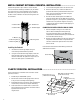
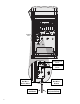
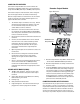
2" Conduit Nut
2" Conduit Nipple
Mounting Plate
½" Conduit Nut
½" Conduit Nut
¾" Washer (4)
³∕8" Mounting Nut (8)
³∕8" Mounting Bolt (8)
Installing the Pedestal
1. Assemble the mounting template using the
instructions provided with the pedestal.
2. Using the enclosed mounting template, locate the
bolts two inches deep in the concrete pad, in the
locations indicated. The pad can be any size but at
least a two-foot square is recommended.
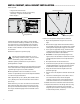
meTal CabIneT opTIonal pedesTal InsTallaTIon .....................
Select a location for installation of the controller based
upon these factors:
1. Availability of 120/230 VAC~ power.
2. Do not locate under overhanging branches of trees
or any structure that may attract lightning.
3. Avoid locations where sprinklers spray upward onto
the controller, and low areas subject to flooding.
4. Locate controller in a location that is central to all
valves/sprinklers that it controls to maintain visible
operation and reduce wire
lengths/costs.
3. Level the mounting bolts before the concrete sets.
4. After the concrete sets, remove the door of the
pedestal and slide the pedestal down onto the four
bolts. Secure the pedestal to the bolts using the
enclosed washers and nuts.
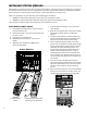
5. Remove the door and faceplate of the ACC and
attach the metal cabinet of the ACC to the top of the
pedestal using the ½" (13 mm) and 2" (50 mm) metal
conduit nuts in the pedestal. Tighten securely by
engaging teeth with a screwdriver and tapping in a
clockwise direction.
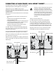
CONNECTING THE METAL PEDESTAL MAIN AC POWER
1. Connect AC power wiring as in the metal wall
cabinet. Route the AC power wiring through
the metal pedestal and up into the ACC wiring
compartment. Follow the AC wiring instructions for
the metal wall cabinet closely.
2. Replace the pedestal door first and then replace the
faceplate and the cabinet door. The pedestal door
cannot be removed or replaced when the cabinet
door is closed.
Refer to Earth Ground and Station Wiring sections for
additional connections.
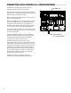
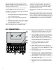
Conduit Nuts
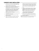
plasTIC pedesTal InsTallaTIon .................................................
AC Power Wire S/P
(3" Max Above Concrete)
GCBL Wiring (Required for IMMS)
(3" Max Above Concrete)
Field Wiring
(3" Max Above Concrete)
Thread Length 2.50" Min
Above Concrete
Template
5.00"
12.50"
26" Min
21" Min
4"