
Operation Manual
7
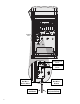
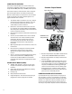
1. Set forms for a 21" (533 mm) wide x 26" (660 mm)
long concrete base. The base pad should be 2" (50
mm) above grade for proper drainage.
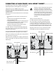
2. Position a 1½" to 3" (38 to 76 mm) diameter conduit
sweep elbow for the field wires (size will vary
depending upon the number of valve wires entering
the controller), a 1" (25 mm) conduit sweep elbow
for the power supply, and a 1" (25 mm) conduit
sweep elbow for any communication wires, if
applicable. Secure the sweeps so they will enter the
bottom of the controller correctly.
3. Allow approximately 3" (76 mm) of conduit above the
surface of the concrete pad.
4. Shape the concrete base to shed any water away
from the controller.
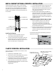
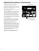
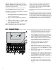
5. Prepare the template for insertion in the concrete.
Twist one nut on each of the four J-bolts to the
ConCreTe base InsTallaTIon ....................................................
bottom of the thread and slide each bolt through the
hole in the template. Put a washer and nut on each
J-bolt to secure it to the template (allow a minimum
of 2½" (63 mm) of thread protruding above each
nut).
6. Work the J-bolts down into the concrete until the
template sits level on top of the concrete. Smooth
and allow the concrete to cure (at least 24 hours).
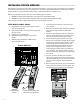
NOTE: It is important with plastic pedestals to
ensure a smooth mounting surface. Uneven
surfaces may cause the pedestal to distort,
preventing proper sealing of the doors.
7. Remove the nuts and washers from the concrete
base. Place the pedestal over the bolts and secure
with nuts and washers.
NOTE: Remove both doors and lift the pedestal from the
main body. Two people are required for this task.