
Operation Manual

10
ConneCTInG earTh Ground (all ConfIGuraTIons) ...................
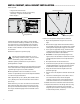
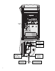
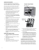
The ACC features a copper earth ground lug, to the
immediate right of the transformer assembly.
This earth ground connection is isolated from the primary
AC power and is used to ground incoming surges from the
communications and output valve wires.
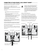
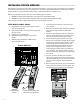
With the controller power Off, loosen the slotted screw in
the center of the ground lug.
Route a bare 6 AWG (4.11 mm) earth ground wire into the
wiring area through the 0.75" (19 mm) conduit opening
directly beneath the ground lug, in the bottom of the
controller cabinet. Do not route the ground wire through
the same conduit as the incoming primary AC power!
Loosen the ground lug screw, insert the ground wire into
the ground lug and tighten the screw to secure the ground
wire. Do not overtighten.
Grounding hardware should be selected according to
standards established by American Society of Irrigation
Consultants Earth Grounding guideline 100-2002
(available at their website, www.asic.org).
Acceptable grounding consists of an 8' (2.5 m)
copper-clad rod or stake, or a 4" x 96" (100 mm x 240 cm)
copper plate, or both, placed in the earth at least 8' (2.5
m) away from the controller, and with the ground wire at
right angles to the communications and valve wires, if
possible. Ideal grounding resistance would be 10 Ohms
or less as measured with a “megger” or similar device.
Please consult the ASIC reference for more detailed
considerations of this critical step.
Improper connection to earth ground voids the
effectiveness of the output module surge protection.
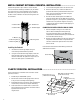
Ground Lug
Ground Wire in
½" (13 mm) conduit