
Operation Manual

13
Each path should consist of Hunter Industries Model
IDWIRE1 or IDWIRE2 color-coded decoder wire. This is
a twisted, solid-core wire suitable for direct burial, and is
always color-coded red and blue.
All red/blue connections in the two-wire path must be
made with DBR6 waterproof connectors or equal.
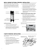
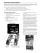
Each path has a red and a blue terminal with its number on
the decoder output module.
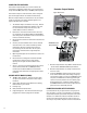
1. Route decoder path wires through the conduit into
the wiring compartment. Leave adequate slack in the
wires for thermal contraction.
2. Strip ½" (13 mm) of insulation from the red and blue
ends.
3. Connect the red wire to the red “1” terminal, and the
blue wire from the same pair to the blue “1”. Repeat
for any other paths as needed.
Do not connect the paths in a loop, or back to any other
point in the controller. Leave the red and blue paths
separate at the end of each two-wire run. Simply insert
decoders in the path until complete, and stop at the
last decoder on the path. If this is not possible, simply
cap each of the ends of the two wire path with a DBR6
waterproof connectors or equal.
Do not connect a wire path from one controller to another
controller!
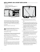
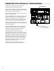
When a decoder output module is installed, the controller
facepack will recognize it and the station size will change
to “99” (regardless of how many stations are in use). This
will also unlock the normally Extended Decoder displays in
the following dial positions. See DECODER OPERATIONS
(ACC99D VERSIONS) on page 56 for more information.
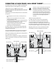
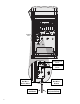
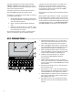
Key ConneCTIons .......................................................................
1. Common Ground Terminals (x 3) – For return wires
(often white) from stations and master valves. Field
wiring may be returned to any of these 3 terminals
2. P/M1 – Pump/Master Valve output 1, and status light
(return Pump/Master valve circuit to any of the 3 Com
common terminals). Output is 0.320 Amps max
3. P/M2 – Pump/Master Valve output 2, and status light
(return Pump/Master valve circuit to any of the 3 Com
common terminals). Output is 0.320 Amps max
4. Hardwire terminal connection cover – Remove
to install optional ACC-HWIM for hardwired
communications.
5. 24VAC – Always-on 24V test terminal, for locating
valves in the field. Can also be used to power low-draw
sensor receivers such as Hunter WRC. Output is 0.420
amps maximum
6. Flow Sensor connections (+ and -) – Connections for
Hunter HFS flow sensor
7. ET connections (+ and -) – Not used. Connections for
Hunter ET Sensor only. If upper ET terminal is colored
red, Master Module requires update for use with ET.
8. If Master Module has a sticker that says “ET Ready,” or
if the version number of the module is 4.0 or later, the
Master Module is ET ready
9. Sensor Connections (1-4) – Connections for up to 4
Clik-family sensors, or other normally closed switch
contacts
1
3
2
4
5
67
8