I n s t a l l a t i o n G u i d e See page 2 ENGLISH Vea la página 21 Español 90063/90064 Ellipse™ Bath Ventilator with Light and Night Light READ and SAVE THESE INSTRUCTIONS 41722-01 3/29/2006 41722_EngS_3.29.03.
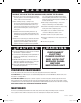
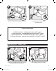
W a r n i n g TO REDUCE THE RISK OF ELECTRIC SHOCK OR INJURY, OBSERVE THE FOLLOWING: 1. Use this unit only in a manner intended by the manufacturer. If you have questions, contact the manufacturer at the phone number or address listed in the warranty. such as those published by the National Fire Prevention Association (NFPA), and the American Society for Heating, Refrigeration and Air-Conditioning Engineers (ASHRAE), and the local code authorities. 2.
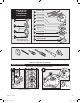
Check all the parts. If damaged, call 1-888-830-1326 for replacements. x5 D E F A G H * B 3/8” Cable Connector x2 I * C x2 I J K Extra Screws relief cable connector * NOTE: Strain must be installed. Not Included. L 95044-01-000 95022-01-000 75190-01-000 03242-07-133 95492-01-000 74508-03-133 95510-01-000 75184-01-133 95366-01/02-000 Included. Tools Needed. (Not supplied) Estimated assembly time: 30 to 60 minutes Before Installation NOTE: Remove all packing materials before installation.
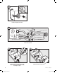
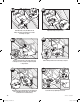
3 H E Remove packing material. Remove the motor/blower from the housing. 5 6 Remove the pre-loaded screw tip covers. 7 G Remove the wiring cover screw. 4 41722_EngS_3.29.03.indd 4 Back out the pre-loaded screw tips until flush with the side of the housing. 8 F Remove the wiring cover.
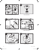
10 9 E C B Pop out the first wiring access slug. Use second if needed. Insert the strain relief into the housing and secure with the washer.
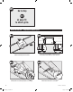
A13 Pull wires through the strain relief. A14 Ground Black Green White A 2 Pin Bare Copper Black Main Switch 1 (AC In) Fan Motor White White Night Light Red Night Light 3 Pin Light Black Light Red Switch 1 (AC In) *Option Black Switch 2 (AC In) *Option Fan & Main Light Together Connect wires as shown. A15 F A16 2 G 1 • F Install the wiring cover plate. Make sure all wiring connections are inside the box or under the wiring cover plate. 6 41722_EngS_3.29.03.
A18 A17 0 H Connect 4” duct and vent to the outside. Tape joints. If ducting does not fit securely, an adapter may need to be purchased. A19 Connect wiring from the motor to the wiring cover plate. A20 H I Reinstall the motor by inserting the tabs and pushing up into position. Make sure the wires are not pinched between the motor and the housing. A21 Secure the motor by tightening the 2 screws. A22 ON OFF Turn on the power source. 41722-01 3/29/2006 41722_EngS_3.29.03.
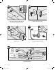
A23 Go to step E1 on page 18 to attach grille. New Construction – suspended between joists B12 B11 E D 5/8 1/2 5/8 1/2 Slide the mounting rails into brackets. B13 Position the correct depth mark at the bottom edge of the joist based on the thickness of your sheetrock. B14 1/8" Bit E Mark position of screws by using holes as a template. 8 41722_EngS_3.29.03.indd 8 Drill a hole in the center of each outline.
B15 B16 Insert screws, leaving space between the screw head and the joist. Screws are not provided. Attach the rails onto the screws. B18 B17 Pull wires through the strain relief. Tighten screws. B19 Ground Black Green White A 2 Pin Fan Motor Light 3 Pin Black Main Switch 1 (AC In) White White Night Light Bare Copper Red Night Light Black Light Red Switch 1 (AC In) *Option Black Switch 2 (AC In) *Option Fan & Main Light Together Connect wires as shown.
B20 F B21 2 G 1 • F Install the wiring cover plate. Make sure all wiring connections are inside the box or under the wiring cover plate. Tighten the wiring cover plate screw. B23 B22 H Connect 4” duct and vent to the outside. Tape joints. If ducting does not fit securely, an adapter may need to be purchased. B24 B25 H Reinstall the motor by inserting the tabs and pushing up into position. Make sure the wires are not pinched between the motor and the housing. 10 41722_EngS_3.29.03.
B27 B26 ON OFF Turn on the power source. B28 Test the motor. If the motor does not run, check the plug connection. Go to step E1 on page 18 to attach grille. Existing Construction – accessible from above C11 NO EXISTING FAN EXISTING FAN OR Remove an existing fan and check to make sure the opening is large enough to accommodate the new motor housing (9”x 9.75”). 41722-01 3/29/2006 41722_EngS_3.29.03.indd 11 Use the motor housing as a template to mark position.
C12 5” D 9. 7 9” E Cut out an opening for the housing. Slide the mounting rails into brackets. C13 C14 5/8 1/2 5/8 1/2 Position the correct depth mark at the bottom edge of the joist based on the thickness of your sheetrock. C15 Mark position of screws by using holes as a template. C16 1/8" Bit Drill a hole in the center of each outline. 12 41722_EngS_3.29.03.indd 12 Insert screws, leaving space between the screw head and the joist. Screws are not provided.
C17 C18 Attach the rails onto the screws. Tighten screws. C20 C19 Connect 4” duct and vent to the outside. Tape joints. If ducting does not fit securely, an adapter may need to be purchased. Pull wires through the strain relief. C21 Tighten the strain relief screws. 41722-01 3/29/2006 41722_EngS_3.29.03.
C22 Ground Black Green White A 2 Pin Bare Copper Black Main Switch 1 (AC In) Fan Motor White White Night Light 3 Pin Light Red Night Light Black Light Red Switch 1 (AC In) *Option Black Switch 2 (AC In) *Option Fan & Main Light Together Connect wires as shown. C23 C24 2 G 1 • F Tighten the wiring cover plate screw. Install the wiring cover plate. Make sure all wiring connections are inside the box or under the wiring cover plate.
C27 C28 I Turn on the power source. Secure the motor by tightening the 2 screws. C30 C29 ON Go to step E1 on page 18 to attach grille. OFF Test the motor. If the motor does not run, check the plug connection. Existing Construction – accessible only from below D11 EXISTING FAN D12 E Remove an existing fan and check to make sure the opening is large enough to accommodate the new motor housing (9”x 9.75”). 41722-01 3/29/2006 41722_EngS_3.29.03.
D13 1 2 D14 Pull wires through strain relief. Attach existing ducting to duct connector. Tape joints. If ducting does not fit securely, an adapter may need to be purchased. D15 E Screw pre-loaded screws into joist or framing. D16 Ground Black Green White A 2 Pin Fan Motor Light 3 Pin Black Main Switch 1 (AC In) White White Night Light Bare Copper Red Night Light Black Light Red Switch 1 (AC In) *Option Black Switch 2 (AC In) *Option Fan & Main Light Together Connect wires as shown.
D18 D17 2 G 1 • F Tighten the wiring cover plate screw. Install the wiring cover plate. Make sure all wiring connections are inside the box or under the wiring cover plate. D20 D19 H H Connect wiring from the motor to the wiring cover plate. D21 Reinstall the motor by inserting the tabs and pushing up into position. Make sure the wires are not pinched between the motor and the housing. D22 I Secure the motor by tightening the 2 screws. 41722-01 3/29/2006 41722_EngS_3.29.03.
D23 D24 ON Go to step E1 on page 18 to attach grille. OFF Test the motor. If the motor does not run, check the plug connection. Attaching the Grille E1 E2 H K L Remove the thumbscrews. E3 Remove glass. E4 H J K Connect wiring harness. 18 41722_EngS_3.29.03.indd 18 Slide light mount over posts and attach thumbscrews. WARNING: To reduce the risk of electrical shock, all 4 thumbscrews MUST be properly installed.
E5 E6 J L Install 2 Max 60 Watt A-15 bulbs (Not Included) and 1 Max 7 Watt C-7 bulb (Not Included). Align glass and push up. Trouble Shooting Problem: Fan does not come on. Solution: • Hunter Fan Bath Ventilators are extremely quiet. To confirm that the fan is running, place your hand near the vents to feel the air movement. • Turn power on, replace fuse, or reset breaker. • Check all plug connections to be sure they are secure. • Check the wiring to make sure it matches the wiring diagram.
Warranty Hunter Fan Company Bath Exhaust Fan LIMITED WARRANTY Hunter Fan Company makes the following limited warranty to the original user or consumer purchaser of this Hunter bath exhaust fan: If any part of your Hunter bath exhaust fan (except for glass fixtures and light bulbs) fails at any time within one year after the date of sale to you due to a defect in material or workmanship, we will repair or, at our option, replace the defective part free of charge for parts and labor performed at our nearest s
DESDE G u í a d e i n s t a l a c i ó n Español Ventilador para baño 90063/90064 Ellipse™ con luz y luz de noche LEA y CONSERVE ESTAS INSTRUCCIONES 41722-02 3/29/2006 41722-Span_3.29.06.
A D V E R T E N C I A PARA REDUCIR EL RIESGO DE DESCARGA ELÉCTRICA O LESIONES, OBSERVE LO SIGUIENTE: 1. Utilice esta unidad sólo de la manera indicada por el fabricante. Si tiene alguna pregunta, contacte con el fabricante en el teléfono o la dirección indicados en la garantía. normas de seguridad, como las de la Asociación Nacional de Protección contra Incendios (NFPA), la Asociación de Ingenieros Americanos en Calefacción y Aire acondicionado (ASHRAE), y los códigos locales. 2.
Verifique todos los componentes. Si están dañados, llame al 1-888-830-1326 para obtener un reemplazo. x5 D E F A G H * B Conector de cable de 3/8” x2 I * C x2 I J K Tornillos adicionales estar instalado el * NOTA: Debe manguito de alivio de tensión L 95044-01-000 95022-01-000 75190-01-000 03242-07-133 95492-01-000 74508-03-133 95510-01-000 75184-01-133 95366-01/02-000 del cable. No incluido. Incluido.
4 3 H E Retire el material de embalaje. Retire el motor/soplador del alojamiento. 5 6 Retire las cubiertas de las puntas de tornillo precargadas. Retire las puntas de tornillo precargadas hasta que estén a nivel con el lado del alojamiento. 7 8 G Retire el tornillo de la cubierta del cableado. 24 41722-Span_3.29.06.indd 24 F Retire la cubierta del cableado.
10 9 E C B Retire el primer tapón metálico de acceso del cableado. Utilice el segundo si es necesario. Introduzca el aliviador de tensiones en el alojamiento y asegúrelo con la arandela.
A13 Tire de los alambres por el aliviador de tensiones. A14 Tierra 22 pasadores clavijas Negro Verde Blanco A Cobre desnudo Negro Interruptor principal 1 (CA) Motor del ventilador Luz de noche Luz Blanco Blanco 33 pasadores clavijas Rojo Luz de noche Negro Luz Rojo Interruptor 1 (CA) *Opción Negro Interruptor 2 (CA) *Opción Ventilador y luz principal juntos Conecte los alambres como se muestra. A15 F A16 2 G 1 • F Instale la placa de cubierta del cableado.
A18 A17 0 H Conecte un ducto de 4” y ventile hacia el exterior. Aplique cinta a las uniones. Si el ducto no se ajusta firmemente, puede ser necesario comprar un adaptador. A19 Conecte el cableado del motor a la placa de cubierta del cableado. A20 H I Vuelva a instalar el motor introduciendo las pestañas y levantando a su posición. Asegúrese que los alambres no se pellizquen entre el motor y el alojamiento. A21 Asegure el motor apretando los 2 tornillos.
A23 Vaya al paso E1 en la página 38 para fijar la rejilla. Construcción nueva – suspendido entre vigas B12 B11 E D 5/8 1/2 5/8 1/2 Deslice los rieles de montaje en los soportes. B13 B14 E Asegure el motor apretando los 2 tornillos. 28 41722-Span_3.29.06.indd 28 Ubique la correcta marca de profundidad en el borde inferior de la viga, según el espesor de su plancha de yeso. broca de 1/8 de pulg. Taladre un agujero en el centro de cada perfil.
B15 B16 Introduzca los tornillos, dejando espacio entre la cabeza del tornillo y la viga. No se proporcionan los tornillos. Fije los rieles en los tornillos. B18 B17 Marque la posición de los tornillos utilizando los agujeros como una plantilla. B19 Tire de los alambres por el aliviador de tensiones.
B20 F B21 2 G 1 • F Instale la placa de cubierta del cableado. Asegúrese que todas las conexiones de cableado estén dentro de la caja o debajo de la placa de cubierta del cableado. Apriete el tornillo de la placa de cubierta del cableado. B23 B22 H Conecte un ducto de 4” y ventile hacia el exterior. Aplique cinta a las uniones. Si el ducto no se ajusta firmemente, puede ser necesario comprar un adaptador. Conecte el cableado del motor a la placa de cubierta del cableado.
B27 B26 ENCE NDIDO APAG ADO Pruebe el motor. Si el motor no funciona, verifique la conexión del enchufe. Encienda la fuente de alimentación. B28 Vaya al paso E1 en la página 38 para fijar la rejilla. Construcción existente – accesible desde arriba C11 SIN VENTILADOR EXISTENTE VENTILADOR EXISTENTE O Retire el ventilador existente y asegúrese que la abertura sea suficientemente grande para acomodar el alojamiento del motor nuevo (9” x 9.75”). 41722-02 3/29/2006 41722-Span_3.29.06.
C12 5” D 9. 7 9” E Recorte una abertura para el alojamiento. Deslice los rieles de montaje en los soportes. C13 C14 5/8 1/2 5/8 1/2 Ubique la correcta marca de profundidad en el borde inferior de la viga, según el espesor de su plancha de yeso. C15 Marque la posición de los tornillos utilizando los agujeros como una plantilla. C16 broca de 1/8 de pulg. Taladre un agujero en el centro de cada perfil. 32 41722-Span_3.29.06.
C17 C18 Fije los rieles en los tornillos. C19 Conecte un ducto de 4” y ventile hacia el exterior. Aplique cinta a las uniones. Si el ducto no se ajusta firmemente, puede ser necesario comprar un adaptador. Apriete los tornillos. C20 Tire de los alambres por el aliviador de tensiones. C21 Apriete los tornillos del aliviador de tensiones. 41722-02 3/29/2006 41722-Span_3.29.06.
C22 Tierra 22 pasadores clavijas Negro Verde Blanco A Cobre desnudo Negro Interruptor principal 1 (CA) Motor del ventilador Luz de noche Luz Blanco Blanco 33 pasadores clavijas Rojo Luz de noche Negro Luz Rojo Interruptor 1 (CA) *Opción Negro Interruptor 2 (CA) *Opción Ventilador y luz principal juntos Conecte los alambres como se muestra. C23 C24 2 G 1 • F Instale la placa de cubierta del cableado.
C27 C28 I Encienda la fuente de alimentación. Asegure el motor apretando los 2 tornillos. C30 C29 Vaya al paso ENCE NDIDO E1 APAG ADO C27 en la página 38 para fijar la rejilla. Pruebe el motor. Si el motor no funciona, verifique la conexión del enchufe. I Construcción existente – accesible sólo desde abajo D11 VENTILADOR EXISTENTE D12 E Retire el ventilador existente y asegúrese que la abertura sea suficientemente grande para acomodar el alojamiento del motor nuevo (9” x 9.75”).
D13 1 2 D14 Tire de los alambres por el aliviador de tensiones. Conecte el ducto existente con el conector de ducto. Aplique cinta a las uniones. Si el ducto no se ajusta firmemente, puede ser necesario comprar un adaptador. D15 E Instale los tornillos precargados en la viga o el marco.
D18 D17 2 G 1 • F Instale la placa de cubierta del cableado. Asegúrese que todas las conexiones de cableado estén dentro de la caja o debajo de la placa de cubierta del cableado. Apriete el tornillo de la placa de cubierta del cableado. D20 D19 H H Conecte el cableado del motor a la placa de cubierta del cableado. D21 Vuelva a instalar el motor introduciendo las pestañas y levantando a su posición. Asegúrese que los alambres no se pellizquen entre el motor y el alojamiento.
D23 D24 ENCE NDIDO Vaya al paso E1 en la página 38 para fijar la rejilla. APAG ADO Pruebe el motor. Si el motor no funciona, verifique la conexión del enchufe. Fijación de la rejilla E1 E2 H K L Retire el domo. Retire los tornillos de mano. E3 E4 H J K Deslice el soporte sobre los postes. 38 41722-Span_3.29.06.indd 38 Instale los tornillos de mano. ADVERTENCIA: Para reducir el riesgo de descarga eléctrica, los 4 tornillos de mano DEBEN instalarse apropiadamente.
E6 E5 J L Instale 2 bombillas A-15 de 60 vatios como máximo (No incluidas) y 1 bombilla C-7 de 7 vatios como máximo (No incluida). Alinee el domo y levante. Solución de problemas Problema: El ventilador no está operando. Solución: • Los ventiladores de baño Hunter son muy silenciosos. Para confirmar que el ventilador esté funcionando, coloque su mano cerca de los conductos de ventilación para sentir el movimiento del aire.
Garantía Hunter Fan Company Extractor de aire para baño GARANTÍA LIMITADA Hunter Fan Company establece la siguiente garantía limitada al usuario o comprador original de este Extractor de aire para baño Hunter: Si alguna pieza de su Extractor de aire para baño Hunter (con excepción de las lámparas de vidrio y las bombillas) falla en cualquier momento dentro de un año después de la fecha de compra debido a una falla de material o mano de obra, repararemos o, a nuestra elección, reemplazaremos la pieza defectu