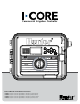
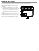
Commercial Irrigation Controller RAIN SENSOR ACTIVE BYPASS SYSTEM OFF MANUAL OPERATION SETTINGS ADVANCED FEATURES SET SENSOR OPERATION CYCLE AND SOAK Owner’s Manual and Installation Instructions IC-600PL 6-station Controller expandable to 30 stations, Plastic Cabinet IC-600M 6-station Controller expandable to 42 stations, Metal Cabinet IC-600PP 6-station Controller expandable to 42 stations, Plastic Pedestal IC-600SS 6-station Controller expandable to 42 stations, Stainless Steel SET CURRENT DATE / TIM
SET CURRENT DATE / TIME SET PROGRAM START TIMES SET STATION RUN TIMES SET DAYS TO WATER SET SEASONAL ADJUSTMENT SET PUMP OPERATION
Table of Contents Introduction............................................................................................ 2 I-Core Interface and Key Components.............................................. 2 I-Core Wiring Compartment and Interior......................................... 3 Mounting the Controller to Wall..................................................... 4 Wall Mount for Plastic and Metal Cabinet.....................................................
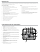
Introduction The Hunter I-Core controller is a full-featured controller for demanding commercial and high-end residential applications. Versatility is what makes the I-Core one of Hunter’s highest performing irrigation controllers. I-Core features include: Note: • Modular design expandable from 6 to 30 stations (plastic cabinet) and 6 to 42 stations (metal/stainless cabinet) - This product should not be used for anything other than what is described in this document.
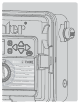
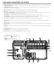
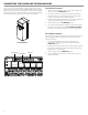
I-Core Wiring Compartment and Interior 1. attery Compartment (9-volt alkaline battery) – The alkaline battery (not included) keeps time during power outages. The user may also program the B controller without AC power. 2. Battery Compartment (CR2032 3-volt lithium) – The lithium battery provides backup timekeeping during power outages and when the 9-volt is not installed (location is on the back of the facepack). 3.
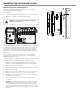
Mounting the Controller to Wall Wall Mount for Plastic and Metal Cabinet A All necessary mounting hardware is included with your controller and should be suitable for most installations. B Tools required: • Long drill bit and extension Philips screwdriver or bit (for use with long extension) – magnetic recommended Wire strippers NOTE: This controller must be installed in compliance with local electrical codes.
Mounting the Controller (Metal Pedestal) Pedestal Mount for Metal/Stainless Cabinet Location Requirement: A) A switch or circuit-breaker shall be included in building installations; B) the switch or breaker shall be in close proximity to the controller, and within easy reach of the operator; C) the switch or breaker shall be marked as the disconnecting device for the controller; D) the switch or circuit breaker used must comply with IEC 60947-1 and IEC 60947-3.
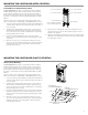
Connecting ac power NOTE: It is recommended that a licensed electrician perform the following power installation. The I-Core can operate with either 120VAC or 230VAC power. Supply wires must be 14AWG or larger. 1. Turn AC power off at the source, and verify that it is off. 2. Remove the cover from the junction box. 3. Strip approximately ½" (13 mm) of insulation from the end of each of the AC power wires. 4. Route the wires through the conduit opening inside the junction box.
Connecting Earth Ground The I-Core features a ground lug, which is isolated from the primary AC power, and is used to ground incoming surges from the communications and output valve wires. Do NOT connect the primary AC 120/230V electrical ground wire to the earth ground lug. 1. 2. se #10 (6 mm) or #8 (10 mm) bare wire to connect the controller U to the ground rod. Route the earth ground wire into the wiring compartment through the 1 ½" conduit opening at the bottom of the cabinet.
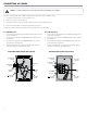
Connecting the Power and Station Modules The I-Core controller is supplied with one factory installed power module and one station module for six stations. Additional station modules may be added in six station increments to expand the controller’s station capability. The plastic cabinet I-Core can be expanded to a size of 30 stations, and the metal cabinet and plastic pedestal I-Core can expand to 42 stations. Station Module Installation 1. pen the inner facepack door and locate the Slide Lock.
Connecting Valve Wires Connecting Station Valve Wires Each station output is rated for 0.56A max, or enough to operate two Hunter AC solenoids simultaneously. The Master Valve or Pump Start Relay connection is located on the bottom row of the Power and Accessory Terminals, and is labeled P/MV. This terminal will supply 24 VAC, 0.32A max, for a single Master Valve solenoid. For a Pump Start Relay, the relay holding current draw must not exceed 0.28 amps.
Connecting a Weather Sensor (Optional and Not Included) The I-Core controller has the ability of connecting two Hunter Sensors (three with I-Core Metal) including: • Mini-Clik® • Rain Clik™ (including Wireless Rain Clik, Wireless Rain Freeze-Clik) • Freeze-Clik® • Wind-Clik® • Mini-Weather Station (MWS) • Solar Sync and Wireless Solar Sync ET Sensor With the I-Core controller, Clik sensors can be programmed to shut down individual stations, not necessarily the entire controller.
Connecting a Hunter Solar Sync The Solar Sync is a “smart“ control system that, when connected to the I-Core, will automatically adjust your controller’s station run times based upon changes in local climate conditions. The Solar Sync incorporates a solar and temperature sensor to determine evapotranspiration, also known as ET. It also utilizes a Rain Clik and Freeze-Clik to shut down your irrigation when conditions arise. The I-Core now has the Solar Sync software built into the controller.
Connecting a Flow Sensor (optional) The I-Core is designed to operate primarily with the Hunter HFS Flow Sensors. However, some non-Hunter flow sensors can be used. 1. To connect a Hunter HFS Flow Sensor, route the pair of 18 AWG (1 mm) wires from the sensor into the cabinet (max distance of 1,000 ft.). 2. L ocate a pair of S1 or S2 (S3 available on I-Core Metal) sensor red and black terminals on the Power and Accessories Terminals. Remove the jumper wire from one pair or S1 or S2 terminals.
Connecting a Remote Control (Optional) The I-Core controller has factory installed SmartPort®. This provides a remote ready connection for Hunter ICR, ROAM, and SRR remotes. To connect a remote, remove the weather resistant rubber cover on the SmartPort, align the remote receiver’s pins with the connector, and push firmly until the receiver is fully seated. Refer to the remote control owner's manual for further information on how to operate your Hunter remote.
Power Failures Due to the possibility of power failures, the I-Core has nonvolatile memory to preserve programming data indefinitely. The 9-volt battery is required for programming of the controller in the absense of AC power. Both the 9-volt battery and lithium battery (if a 9-volt battery is not installed), will maintain the current time and day during power outages. If the power goes out, the display will acknowledge there is No A/C Power.
Controller Programming Setting Current Date and Time The Set Current Date and Time dial position allows you to set the current date and time in your I-Core controller. 1. Turn the dial to the SET CURRENT DATE/TIME position. 2. he year will be flashing in the display. Use the + / – button to change T the year. Press the ► button to proceed. 3. he month will be flashing. Use the + / – button to change the month. T Press the ► button to proceed. 4. he day will be flashing.
Controller Programming (continued) Selecting Odd or Even Days to Water NOTE: When entering run times the Seasonal Adjusted run time will be displayed in the lower right corner of the display. The default Seasonal Adjustment setting is 100%. If the ACTUAL value is different from the PROGRAMMED value, the Seasonal Adjustment has been changed from the default of 100% to a new value. This feature uses numbered days of the month for watering instead of specific days of the week.
Controller Programming (continued) 5. I n the Interval Watering mode, there will be a No Water Days description on the display. Within the Interval Watering mode you can select days that watering will not take place. This is a feature that is frequently used to omit watering on a specific day, for example, a mowing day. Press the ▼ button until the cursor points to Monday. Once the cursor points to Monday the No Water Days description will start flashing.
Controller Programming (continued) he Solar Sync will take over and the percentage will change according to T the findings of the Solar Sync sensor. If you set seasonal adjust mode to Solar Sync and you DO NOT have a Solar Sync connected, the controller will automatically keep the seasonal adjust percentage at 100%. here are also further steps in programming of the I-Core to assign the T Solar Sync, Rain, and Freeze sensor to shut down specific stations.
Controller Programming (continued) Rotate the dial to the SET SENSOR OPERATION position. Both sensors programmed for Station 1 Sensor 1 only programmed for Station 1 1. Use the ◄ and ► buttons to select the station that you would like to program a sensor response. 2. he default is to have the sensor input active for each station, T therefore indicating a . The cursor will be flashing on either SEN1 or SEN 2. Use the + button to enable sensor operation or the – button to disable the sensor. 3.
Controller Programming (continued) a remote, the controller will acknowledge the stations that have been programmed to respond to a sensor and those stations will not water and be in Suspend Mode. The same rules apply for activating a station or program manually by turning the dial to the manual position. A manual single station will override an active sensor; however, a manual program will adhere to the rules of shutting down irrigation if the station within the program is set to respond to the sensor.
Controller Programming (continued) If the user has not selected a station’s flow to be monitored the controller will display No Flow Station, as well as No Runtime even if there is a run time associated with the stations. Once the correct station number is displayed, turn the dial to Run. Again, the controller will go into its diagnostic flow testing for that particular station. The controller will activate the station and the learning process may take up to a minute.
Advanced Features Advanced features can be accessed by turning the dial to the Advanced Features dial posiiton. Use the ▲ or ▼ buttons to navigate through the Advanced Feature selections. When the ► cursor is pointing to the selection you want, simply press the + button to select the feature. Use the ◄ button to go back to the previous menu. A detailed description of each selection within the Advanced Features are provided below.
advanced features (continued) Use the ▲ or ▼ buttons and the ◄ and ► buttons to navigate through the Custom, K-Factor, and Offset screen. Once you navigate to a number, it will flash. The number may be changed by pressing the + / – button to either increase or decrease the value. Once you have completed entering the K-Factor and Offset specified by the manufacturer of the flow sensor, use the ▼ button to return to the main Sensor Configuration screen.
advanced features (continued) Station Delay This feature allows the user to insert a delay time between when one station turns off and the next station turns on. This is very helpful on systems with slow closing valves, or on pump systems that are operating near maximum flow or have slow well recovery. Different time delays between stations can be set according to each Program (from 1 second to 9 hours).
advanced features (continued) To save your watering program into memory: 1. Turn the dial to the Advanced Features position. Use the ▲ and ▼ to select Easy Retrieve Memory and use the + button to enter. 2. Use the ▲ or ▼ buttons to place the ► cursor next to Save. 3. Press the + button once, then press and hold the + button to confirm that you want to save the current programming as the Easy Retrieve program.
advanced features (continued) LCD Adjust The LCD Adjust feature allows you to increase or decrease the contrast of the display. This is helpful to make the display more visible in varying light conditions. You may adjust the contrast of the screen until you are able to read it effectively. 1. Turn the dial to the Advanced Features position. Use the ▲ and ▼ buttons to select LCD Adjust and use the + button to enter. 2.
programming solar sync settings The table will assist you in identifying the type of region you live in. There are four basic ET regions, each with descriptions of the region, along with typical ET and temperature characteristics. It is recommended that, if possible, the region be chosen based upon average July ET or peak summer ET (inches/mm per day). Use the following table for choosing your region (reference below).
programming solar sync settings (continued) Clearing ET memory Programming Solar Sync Delay 1. Once the Solar Sync Sensor is installed the controller will begin collecting ET data. This ET data can be erased/cleared if desired. 2. Turn the dial to the SOLAR SYNC SETTINGS dial position. 3. Use the ▲ and ▼ buttons until the cursor is at Clear ET History. 4. Press the + button to. The following will be shown on the display, clear ET History and Press + to confirm. 5.
Hidden Features Programmable Rain Off The Programmable Rain Off allows the user to set period of time in which the controller will be turned off, after which the system will automatically return to automatic irrigation. This is useful for halting irrigation when weather fronts or conditions are expected to persist for several days. To set a Programmable Rain Off duration: 1. Turn the dial to the OFF position. The stations run time will be flashing.
Hidden Features (continued) 4. or non-Hunter flow sensors, Custom 1, Custom 2, or Custom 3 (Metal F Version I-Core) can be selected as a flow sensor type. With custom selected, press the ► button to program the K-Factor and Offset that is specific to that sensor, specified by the flow sensor manufacturer. 5. Use the ▲or ▼ buttons and the ◄ or ► buttons to navigate through the Custom, K-Factor, and Offset screen.
Controller Diagnostics and Troubleshooting System Status Dashboard Station Status The System Status Dashboard is a quick reference indicator that uses LED lights to provide system status information regarding sensor status, valve operation, and flow monitoring. The Station System Status light monitors and indicates whether a station is operating normally or if an overcurrent condition for a particular station has occurred.
Controller Diagnostics and Troubleshooting (continued) Once a minute has passed, the controller will again activate the station (the display will still indicate that it is Isolating the Flow Alarm). After the Start Up delay has elapsed, if the station flow resembles the learned flow, the controller will continue to run the station for the given programmed run time, and the Sensor Status Light will change to GREEN.
Hunter Quick Check™ The Hunter Quick Check is an efficient and effective way to diagnose problems in the field. Instead of having to physically check each field wiring circuit for potential problems, the user can run the Hunter Quick Check circuit test procedure. This circuit diagnostic procedure is very beneficial to quickly identify “shorts” commonly caused by faulty solenoids or when a bare common wire touches a bare station control wire.
Troubleshooting Problem Causes Solutions No display. Check AC power to controller. Fix power supply. 14-Pin connector is not fully connected. Connect ribbon cable on back of facepack door. Module locking bar is in the Power Off position. Slide the module locking bar into the Power On position. The display reads NO A/C Power. No AC power present to operate controller/valves. Check to see if the transformer is properly installed or power is coming out of it.
Troubleshooting Problem Causes Solutions Rain or other Clik sensor does not shut down system. Incorrect sensor type or connection (Jumper installed). Use one normally-closed Clik-type sensor per sensor ports. Verify that one wire from each sensor is to each SEN1 or SEN2 terminals. Remove Jumper wire. Incorrect sensor settings for stations. Turn dial to Set Sensor Operation and verify correct response for each station to the sensor.
I-Core: Institutional/Commercial Controller (IC-600PL & IC601PL) – Plastic Cabinet Item Description Catalog No.
I-Core: Institutional/Commercial Controller (IC-800M & IC-800SS) – Metal Cabinet Item Description Catalog No.
3 I-Core Plastic Pedestal 2 1 Item Description Catalog No.
Specifications Operating Specifications • Station Run Time: 1 minute to 12 hours (in 1-minute increments) on programs A, B, C, D. • Start Times: 8 per day, per program (A, B, C), 16 per day (D), for up to 40 daily starts. • Watering Schedule: 7-day calendar, interval watering up to a 31-day interval or true odd or even day programming, made possible by the 365-day clock/calendar.
notes ___________________________________________________________________________________________________________________________________________ ___________________________________________________________________________________________________________________________________________ ___________________________________________________________________________________________________________________________________________ ______________________________________________________________________________________
41
Hunter Industries Incorporated • The Irrigation Innovators 1940 Diamond Street • San Marcos, California 92078 USA www.hunterindustries.