WVC OWNER’S MANUAL & INSTALLATION INSTRUCTIONS Wireless Valve Controller Multiple-Station, Battery-Powered Irrigation Controller
Introduction The Hunter Wireless Valve Controller (WVC) is a batterypowered, radio programmable controller that can operate one (WVC-100), two (WVC-200), or four (WVC-400) valves. Hunter’s wireless, battery-powered irrigation systems are ideal for commercial/municipal applications such as street and highway landscaping, medians, parks, construction sites, and other areas that do not have access to power. The following instructions provide information on installing and setting up your WVC.
Table of Contents Table of Contents 2 Introduction 3 Table of Contents 4 WVC Components 5 Installing the Battery 6 Wiring DC Latching Solenoids to the WVC 7 Radio Communication 8 Addressing the WVC With the WVP 9 Mounting the WVC to a Hunter Valve 13 Notices 13 ..... FCC Notice 14 ..... Industry Canada Notice 15 Notes 10 Alternate Mounting Methods 11 Connecting a Weather Sensor 12 Specifications 12 ..... Operating Specifications 12 ..... Electrical Specifications 12 .....
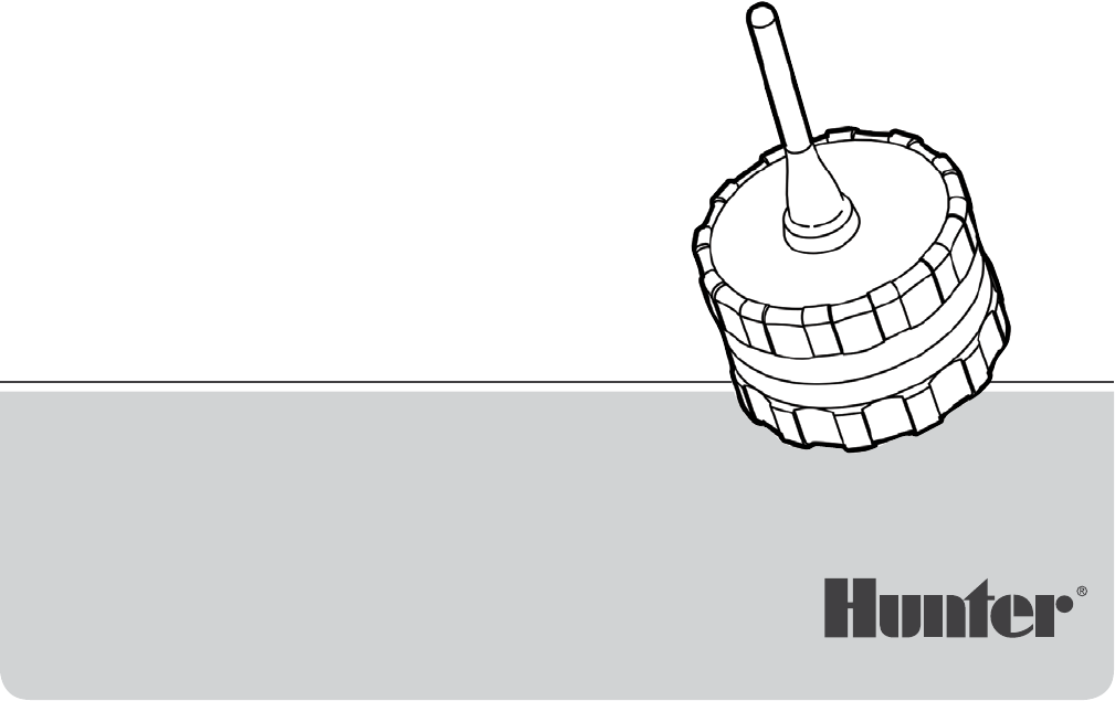
WVC Components This section provides an overview of the components of the WVC. Each item will be discussed in further detail later. However, this section can be helpful in getting acquainted with the available options. 1. WVC Body – The WVC controller is designed to be dirt tolerant, waterproof, and submersible to 12' (3.7 m). 2. External Antenna – Flexible rubber antenna for radio communication. 3. 9-Volt Battery Holder – The WVC is designed to operate on a single 9-volt alkaline battery.
Installing the Battery The WVC uses a standard 9-volt alkaline battery to operate the valve and program the controller. Battery life is affected by the number of valve actuations, along with Note: The battery holder is designed so that the battery can only be inserted in one direction. the distance the solenoids are from the controller. Under normal service conditions the battery should provide at least one full year of service.
Wiring DC Latching Solenoids to the WVC Leads are provided to attach a Hunter DC latching solenoid or other two-wire, low-voltage latching solenoids to the WVC (Hunter DC latching solenoid part #458200). Hunter DC latching solenoids have two leads: one colored black and the other red. To Connect DC Latching Solenoids 1. Select the appropriate station wire (red wire) on the WVC. Note: Station numbers are identified on top of the WVC. Strip away ½" (13 mm) of insulation from the station wire.
Radio Communication All programming and manual operations with the WVC can be controlled with the WVP. Actual performance varies depending upon the installation and the surrounding terrain. The WVP can send/retrieve data to/ from the WVC up to 100' (30 m) with the WVC installed in the valve box below ground level. Radio range increases when the WVC is installed above ground. (Refer to the WVP Owner’s Manual regarding radio communication).
Addressing the WVC With the WVP WVP required to perform this function 4. Install a standard 9-volt alkaline battery into the battery holder (see Connecting the Battery). Each WVC controller requires a unique identification number for proper radio operation with the WVP. Setting unique addresses for each WVC allows for separate radio programming and manual operations with individual WVC controllers even though other controllers may be in the surrounding area.
Mounting the WVC to a Hunter Valve The WVC can easily be mounted on any Hunter plastic valve. A specially designed valve mounting clip makes installation a snap. To Mount the WVC to a Valve (Figure 2) 1. Unscrew the existing solenoid from the valve. 2. Screw the WVC latching solenoid into the valve bonnet. Note: When mounting the WVC, position the antenna vertical and as high as possible in the valve box to achieve maximum range for radio communication. 3.
Alternate Mounting Methods A universal mounting clip and mounting adapter are also provided with the WVC. These accessories provide for alternate methods of mounting the controller either to the side of the valve box or stake mounted within the valve box. Stake Mounting Method (Figure 4) Valve Box Mounting Method (Figure 3) 2. Drive the pipe into the ground inside the valve box to position the WVC to the desired height. 1. Position the universal mounting adapter on the side of the valve box.
Connecting a Weather Sensor Connecting a Weather Sensor Programming the Controller A Hunter Mini-Clik® rain sensor or other micro-switchtype weather sensor can be connected to the WVC. The purpose of this sensor is to stop watering when weather conditions dictate. The WVC is simple to program with its companion, the WVP Wireless Valve Programmer.
Specifications Operating Specifications Electrical Specifications • Station run time: 0 to 4 hours in 1-minute increments • Selenoids: Operates 6- to 9-volt DC latching solenoids • Start times: 9 per day • Battery: Standard 9-volt alkaline battery (not included), one year minimum life. Battery not required for program backup.
Notices FCC Notice This notice applies only to models WVC-100, WVC-200, and WVC-400. The user is cautioned that changes and modifications made to the equipment without the approval of the manufacturer could void the user’s authority to operate this equipment. FCC ID: M3UWVC This equipment has been tested and found to comply with the limits for class B digital device, pursuant to part 15 of the FCC Rules.
Notices Industry Canada Notice This notice applies only to models WVC-100, WVC-200, and WVC-400 IC: 2772-WVC The term “IC:” before the certification/registration number only signifies that the Industry Canada technical specifications were met. Operation is subject to the following two conditions: (1) this device may not cause interference, and (2) this device must accept any interference, including interference that may cause undesired operation of the device.
Notes 15
Helping our customers succeed is what drives us. While our passion for innovation and engineering is built into everything we do, it is our commitment to exceptional support that we hope will keep you in the Hunter family of customers for years to come. Gregory R. Hunter, CEO of Hunter Industries RESIDENTIAL AND COMMERCIAL IRRIGATION | Built on Innovation® Hunter Industries Incorporated 1940 Diamond Street, San Marcos, California 92078, USA www.hunterindustries.