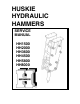
HUSKIE HYDRAULIC HAMMERS SERVICE MANUAL HH1500 HH2000 HH3600 HH4500 HH5800 HH8000 1
CONTENTS 1. Safety Information Page 3 Safety Decals Safety Symbols 2. Operating Instructions Page 6 How the Hammer Operates Mounting the Hammer to Carrier Connecting Hoses Daily Inspection before Operation Initial Startup, Hammer Break-in General Operation Instructions Cold Weather Startup and Operation Underwater Operation Storage Tool Replacement 3.
1. SAFETY INFORMATION • • • • • • • • • • • • • • • • • • • • • Always read the information in this manual before operating the hammer. Failure to do so can result in personal injury or damage to the equipment. Check that all safety decals attached to the hammer and carrier are legible. Replace worn or illegible decals. Do not use drugs or alcoholic beverages that impair alertness or coordination while operating the carrier or hammer.
SAFETY DECALS The decals shown below are attached to the hammer when shipped from the factory. Read and understand them before operating the hammer. Replace any decal that has become worn, damaged or illegible. Decals can be ordered through the parts department. CAUTION DANGER This symbol may appear on the hammer or in the text of this manual. It is used to alert the operator of an action that can place him/her or others in a life threatening situation.
The notice below is included in the shipping carton. It contains information relating to operator safety. Read and understand this notice before unpacking or operating the hammer. We suggest you retain this notice and include it in your local safety program. CAUTION Never operate the hammer unless the following Safety Instructions have been read and understood. • • • • • • Projectiles from the hammer, tool, rock or other broken material may enter the operator’s area and cause serious or fatal injury.
2. OPERATING INSTRUCTIONS HOW THE HAMMER OPERATES On larger hammers the main valve is contained in the valve box, which is bolted to the cylinder (Figure 1). During the upward stroke, the pressure in the upper chamber is released via the main valve and through the outlet. High pressure in the lower chamber then forces the piston upward. As soon as the piston reaches the upper end of the stroke, the main valve directs flow to the upper chamber causing it to become high pressure.
MOUNTING THE HAMMER TO THE CARRIER 1. Skid Steer Loader All hammers are mounted to hammer brackets, which are then mounted to an adapter plate using two pins. The adapter plate is mounted to the quick mount of the carrier. To remove the hammer, first disconnect the hydraulic couplers from the inlet and outlet ports and detach the quick mount. Seal off all plugs and hoses to prevent dust, dirt and foreign particles from entering the system. 2.
INITIAL STARTUP, HAMMER BREAK-IN New or rebuilt hammers require 20-40 minutes of operation at half the rated speed as a break-in period. This allows for proper lubrication of all moving parts and for all sliding surfaces to mate properly. GENERAL OPERATING INSTRUCTIONS 1. Never apply the tool with a side load. The tool must always be pressed firmly against, and be perpendicular to the material to be broken. Failure to do so can cause tool or seal failure. 2.
UNDERWATER OPERATION Operation of hydraulic hammers under water requires proper preparation to prevent internal damage to hammer parts and carrier hydraulic system. 1. To prepare the hammer for underwater operation you will need an external compressed air supply. 2. Connect air supply line to front cap threaded port (remove plug P/N 3Z01-FP0038 as shown.) Thread is 3/8-inch pipe tapered. 3. Set pressure regulator to 50 – 90 psi. 4. Maintain air supply to hammer at all times when operating under water 5.
STORAGE 1. Short Term If the hammer will not be used for periods of one week or more, the tool should be removed from the hammer and grease must be applied to the piston bottom. The hammer should be stored indoors standing vertically in the working position. 2. Long Term For storage of more than 2 - 3 weeks or where condensation or corrosion is prevalent (salt-water areas) note the following instructions. Remove and clean the tool. Flush the front cap with clean solvent or hydraulic oil.
Carefully drive out the tool spring pin. Push the tool set pin up and out of the front cap using a screwdriver or round bar. Note: Check Table 1, Page 10, before handling tools. For models HH100 through HH750-2, manual removal is possible. For hammer models HH1000-2 and larger use hoist and sling as shown. Check for sling load rating and compare to Table 1, Page 10. • When installing the tool in the hammer, reverse steps 1 through 4 above.
3. MAINTENANCE HYDRAULIC OIL Note: It is not recommended to mix types of hydraulic oils. Check carriers hydraulic oil recommendations before adding hydraulic oil. 1. Check the oil level, oil filter condition and oil cooler in the carrier periodically. 2. Replace the hydraulic oil every 600 hours and the filter every 100 hours, or according to carrier recommendations. 3. Always be aware of any abnormalities in the operation of the hammer such as changes to hammer blow speed, impact force or oil temperature.
FASTENERS Inspect all bolts and nuts for tightness. Tighten as required. (Refer to Table 4.) Replace all missing or damaged fasteners before operating the hammer. Fastener bolt and nut sizes are listed in Table 3. These are wrench sizes (distance across flats.) NIPPLES (mm.) BRACKET BOLTS (mm.) 1500 36 2000 HAMMER Table 3. Bolt Sizes VALVE BOX SIDE LIFTING SET *CAP RODS EYES BOLTS (mm.
Table 4. Tightening Torque Requirements (Ft. lbs.) HH1500 HH2000 HH3600 Side Rod 880 ±35 880 ±35 1100 ±35 1850 ±75 2560 ±75 3300 ±75 Valve Box Set Bolt 280 ±20 280 ±20 330 ±20 330 ±20 590 ±35 590 ±35 Valve Cap Bolt 175 ±20 280 ±20 330 ±20 330 ±20 480 ±35 480 ±35 Mode Valve Set Bolt N/A 70 ±3 70 ±3 70 ±3 Bracket Bolt 400 ±35 840 ±35 5 1 1 HH4500 HH5800 70 ±3 70 ±3 1320 ±35 2600 ±35 2600 ±35 2600 ±35 3 7 1 3 5 3 1 4 4 2 Side Rod Back Nut.
NITROGEN (N2) GAS PRESSURE ADJUSTMENT The hammer will not operate properly and may not start due to an incorrect gas charge. Follow the procedure described below to adjust nitrogen (N2) gas pressure. WARNING! DO NOT STAND NEAR THE HAMMER WHEN ADDING NITRIGEN. THE TOOL MAY EJECT SUDDENLY AND CAUSE SEVERE INJURY. 1. Gas Pressure Testing. a.
Figure 9. Gas Charger Valve d. Open the main gas valve on the N2 gas container and regulate the N2 gas pressure (see Figure 8.) e. Turn the gas charger “T” handle clockwise and adjust N2 gas pressure in the gas chamber to the correct gas pressure shown on Table 10, Page 26. f. Turn the gas charger “T” handle fully counter clockwise and remove the hose. Attach the cap to the gas inlet of the charger. g.
Figure 10. GAS LEAKAGE INSPECTION Gas leakage can be easily detected using soapy water (refer to Table 6 and Figure 11.) Table 6.
4. DISASSEMBLY AND ASSEMBLY DISASSEMBLY 1. Tool Refer to tool replacement procedures on Figure 4, page 11. 2. Back cap Support the cylinder (Figure 12). Loosen and remove four side rods and washers, then remove the back cap. 3. Front cap (See Table 3 page 13 for eyebolt sizes) Install an eyebolt and suspend the front cap as shown in Figure 12. Pull out the front cap, being careful not to damage the piston. Figure 12. Connecting Hoist to Front Cap.
4. Main Valve Box Assembly Service of the Valve Box includes the Mode Valve Assembly and the Main Valve with Box Sleeve. a. Remove six or eight (depending on hammer model) Valve Box (4) Set Bolts and place Valve Box on a clean flat service. Note: Inspect o-rings located at ports on cylinder and replace o-rings as necessary. When re-installing Valve Box check that all o-rings are in correct position. b. Remove four Mode Valve (1) Set Bolts and replace o-ring seals as necessary. c.
5. Piston (See Table 7 for Piston weights) Note: For large hammers, you may wish to stand the hammer upright with proper support, and pull the piston upward using a lifting device. a. Attach an eye bolt to the top of the piston and pull out together with cylinder sleeve toward the top. b. It may be useful to use a pry bar as a lever as shown in Figure 14. Be careful to not damage the piston. Figure 14. Removing the piston. 5. Cylinder sleeve Note: Support piston on wood blocks.
INSPECTION OF PARTS 1. Seals Seals that are deformed, scratched, worn or aged should be replaced (see Figure 16). It is recommended that all seals be replaced when disassembling the hammer. Figure 16. Seal Conditions 2. Moving parts Check for any scratches or damage on the surface of the piston, cylinder sleeves, main valve and bottom part of the piston where it strikes the tool. Significantly damaged or scratched parts must be replaced. 3. Front cap a.
5. Replacing the shank bushing Note: Replacement of the front cap bushing is required when replacing the shank bushing, as the front cap bushing must be removed to replace the shank bushing. a. Measure the shank and front cap bushing; refer to Table 8 page 23 and Table 9 page 24. b. Remove bushing spring pin and bushing set pin for shank bushing on the front cap using a punch and hammer. c. Press out shank bushing from the cylinder side together with front cap bushing using a round bar.
COMPONENT WEAR LIMITS Parts are to be replaced if not within the wear parameters. See Table 8 and Figure 17 below, for new dimensions see Table 9 page 24. Table 8. Component Wear Limits COMPONENT Front cap bushing Shank bushing WEAR LIMITS When the clearance between the tool and the front cap bushing exceeds .300 in. (8mm), a new front cap bushing is required. (Approximately 500 hours of use). When the clearance between the tool and the shank bushing exceeds .160 in. (4mm), a new shank bushing is required.
Table 9. New Component Dimensions PART Front Cap Bushing I.D. Shank Bushing Tool I.D. O.D. HH1500 101. mm. 3.967 in. 101. mm. 3.967 in. 100. mm. 3.937 in. HH2000 116. mm. 4.567 in. 116. mm. 4.567 in. 115. mm. 4.528 in. HH3600 HH4500 136. mm. 146. mm 5.354 in. 5.748 in. 136. mm. 146. mm. 5.354 in. 5.748 in. 135. mm. 145. mm. 5.315 in. 5.709 in. HH5800 156. mm 6.142 in. 156. mm 6.142 in. 155. mm 6.102 in. HH8000 166. mm 6.535 in. 166. mm 6.535 in. 165. mm 6.496 in.
8. Insert and tighten the four side rods together with the washer to the specified torque (see Table 4 and Figure 5 on page 14.) 9. Refill the hammer with Nitrogen (N2) gas. Refer to pages 15 and 16. Make sure that the piston is positioned at the lower end of its stroke before charging. The piston and the cylinder may be damaged during gas charging by sudden movement (due to a pressure increase) if the piston is not at the bottom of its stroke in the cylinder.
5. SPECIFICATIONS Table 10. Specifications ITEM UNIT HH1500 HH2000 HH3600 HH4500 HH5800 HH8000 Impact energy ft-lbs. kg-m 1500 2000 3600 4500 5800 8000 Blows per minute bpm 480-550 400-650 300-500 480-630 380-500 480-625 350-450 Required oil flow gpm l/min 21.3-28.7 80-108 21.3-36.
6. REFINISHING OF PISTONS & CYLINDERS If the pistons and cylinders should be scored or scratched due to dirty oil, or improper hydraulic oil specifications, the piston and cylinder can in many cases be polished and salvaged, instead of being replaced. This is possible because the components in this hammer are made of high quality alloy steel and do not use chromium surface finishes which cannot be polished. Follow the procedures in Figures 19, 20 & 21 and finish by thorough flushing and cleaning.
7. TROUBLESHOOTING DIAGNOSIS Table 11.
8. WARRANTY GUIDE LINES Time based on total man-hours.
IPC Industries, Inc. 194 N. Brandon Dr. Glendale Heights, IL 60139 LIMITED WARRANTY FOR HYDRAULIC HAMMERS LIMITED WARRANTY The manufacturer warrants its Products against defects in material and workmanship. Such LIMITED warranty shall apply to the initial Purchaser only. The BACK-CAP, MAIN BODY and FRONT CAP carry a LIFETIME, UNLIMITED HOURS warranty. All other components (except seals and exclusions listed below) are warranted as follows: THREE (3) YEARS, UNLIMITED HOURS.
Warranty Policy Statement This document explains IPC Industries, Inc. specific policies concerning submission and reconciliation of warranty claims. This document is in addition to and a part of the IPC Industries, Inc. Limited Lifetime Warranty For Hydraulic Hammers that accompanies all new hydraulic hammer products. 1. Warranty Registration Card Each hydraulic hammer is shipped with a Warranty Registration Card. In order to properly process your claim this card must be on file at IPC.
6. Requesting a Returned Goods Authorization (RGA) Before returning a suspected warranty part, call IPC at (800) 487-5431 and our customer service representatives will provide you with a RGA number. Please have the description of the part(s) at hand and the method by which you will be returning the part prepaid to IPC. At that time it may be determined that you need not return the part and IPC may, at its sole discretion, warrant the part without examination.
9.
HH1500 HAMMER ITEM 1 2 3 4 5 6 7 8 9 10 11 12 13 14 15 16 17 18 19 20 21 22 23 24 25 26 27 28 29 30 31 32 33 34 35 36 37 38 39 40 41 42 43 44 45 46 NI NI 47 48 NAME Cylinder Cylinder O-Ring* Cylinder O-Ring* Cylinder O-Ring* Cylinder Sleeve Cylinder Sleeve O-Ring* Quad Ring* Back Up Ring* Step Seal* Step Seal O-Ring* U-Packing* Dust Seal* Drain Plug Choke Plug #1 Choke O-Ring* Plug Plug O-Ring* Choke Plug #2 Plug O-Ring* Piston Valve Box Main Valve Main Valve Inner Sleeve Main Valve Outer Sleeve Main Valve
HH1500 HAMMER Effective 07/05 35
HH1500 HAMMER BRACKET ASSEMBLY PARTS LIST PART NO. ITEM QTY DESCRIPTION MODEL HH1500 1. 3J01-212501 1 Hammer Bracket (R)* 2. ----------------1 Hammer Bracket (L)* 3. 3H01-215502 4 Bracket Bolt 4. Assembly of Item 3 4 Washer 5. Assembly of Item 3 8 Nut 6. 3J01-212504 2 Support Pipe 7. 3H01-TC2000B 10 Top Cap Bolt 8. Assembly of item 7 10 Top Cap Washer 9. Assembly of item 7 10 Top Cap Nut 10.
HH2000 HAMMER UP TO S/N 2K031 SOLD BEFORE 9/96 ITEM 1 2 3 4 5 6 7 8 9 10 11 12 13 14 15 16 17 18 19 20 21 22 23 24 25 26 27 28 29 30 31 32 33 34 35 36 37 38 39 40 41 42 43 44 45 46 47 48 49 50 51 52 NI NI NI NI 53 54 NAME NUMBER Cylinder Cylinder O-Ring* Cylinder O-Ring* Cylinder Sleeve Cylinder Sleeve O-Ring* Gas U-Packing* U-Packing* U-Packing with Back Up Ring* Dust Seal* Drain Plug Piston Valve Box Main Valve Upper Valve Cap Valve Cap O-Ring* Back Up Ring* Valve Cap O-Ring* Lower Valve Cap Locater Pi
HH2000 HAMMER UP TO S/N 2K031 SOLD BEFORE 9/96 39 Effective 07/05
HH2000 HAMMER S/N 3K001 & UP SOLD AFTER 10/96 ITEM 1 2 3 4 5 6 7 8 9 10 11 12 13 14 15 16 17 18 19 20 21 22 23 24 25 26 27 28 29 30 31 32 33 34 35 36 37 38 39 40 41 42 43 44 45 46 47 48 49 50 51 52 53 54 55 56 57 58 59 NI NI NI NI NAME NUMBER Cylinder Cylinder O-Ring* Cylinder O-Ring* Plug Cylinder O-Ring* Buffer Ring* Cylinder Sleeve Cylinder Sleeve O-Ring* Quad Ring* Back Up Ring* Step Seal* Step Seal O-Ring* U-Packing* U-Packing* Dust Seal* Piston Valve Box Main Valve Upper Valve Cap Valve Cap O-Ring*
HH2000 HAMMER S/N 3K001 & UP SOLD AFTER 10/96 Effective 07/05 41
HH2000 HAMMER BRACKET ASSEMBLY PARTS LIST PART NO. ITEM QTY DESCRIPTION MODEL HH2000 1. 3H01-215501 1 Hammer Bracket (R)* 2. ----------------1 Hammer Bracket (L)* 3. 3H01-215502 6 Bracket Bolt 4. Assembly of Item 3 6 Washer 5. Assembly of Item 3 12 Nut NI 3H01-215504-198 2 Support Pipe (Top) 6. 3H01-215505-262 2 Support Pipe (Middle) NI 3H01-215506-162 2 Support Pipe (Bottom) 7. 3H01-TC2000B 10 Top Cap Bolt 8. Assembly of Item 8 10 Top Cap Washer 9. Assembly of Item 8 10 Top Cap Nut 10.
HH3600-2 HAMMER ITEM 1 2 3 4 5 6 7 8 9 10 11 12 13 14 15 16 17 18 19 20 21 22 23 24 25 26 27 28 29 30 31 32 33 34 35 36 37 38 39 40 41 42 43 44 45 46 47 48 49 50 51 52 53 54 55 56 57 58 NI NI NI NI 59 60 S/N 5M1000 & UP NAME NUMBER Cylinder Cylinder O-Ring* Cylinder O-Ring* Cylinder Sleeve Cylinder Sleeve O-Ring* Step Seal with O-Ring* Quad Ring* Back Up Ring* U-Packing* Dust Seal* Piston Valve Box Main Valve Upper Valve Cap Valve Cap O-Ring* Back Up Ring* Valve Cap O-Ring* Lower Valve Cap Locater Pin B
HH 3600-2 HAMMER S/N: 5M1000 & UP Effective 07/05 45
HH3600-2 HAMMER S/N 5M1000 & UP BRACKET ASSEMBLY PARTS LIST PART NO. ITEM QTY DESCRIPTION MODEL HH3600-2 1. 3J01-221501 1 Hammer Bracket (R)* 2. ----------------1 Hammer Bracket (L)* 3. 3J01-221502 8 Bracket Bolt 4. Assembly of Item 3 8 Washer 5. Assembly of Item 3 16 Nut NI 3J01-221504-226 2 Support Pipe (Top) 6. 3J01-221507-298 2 Support Pipe (Middle) NI 3J01-221506-234 4 Support Pipe (Bottom) 7. 3J01-TC3600B 12 Top Cap Bolt 8. Assembly of Item 7 12 Top Cap Washer 9.
HH4500 HAMMER ITEM 1 2 3 4 5 6 7 8 9 10 11 12 13 14 15 16 17 18 19 20 21 22 23 24 25 26 27 28 29 30 31 32 33 34 35 36 37 38 39 40 41 42 43 44 45 46 47 48 49 50 51 52 53 54 55 56 57 NI NI NI NI 58 59 NAME NUMBER Cylinder Cylinder O-Ring* Cylinder O-Ring* Cylinder Sleeve Cylinder Sleeve O-Ring* Quad Ring* Back Up Ring* U-Packing* U-Packing with Back Up Ring* Dust Seal* Step Seal with O-Ring* Piston Valve Box Main Valve Upper Valve Cap Valve Cap O-Ring* Back Up Ring* Valve Cap O-Ring* Lower Valve Cap Locate
HH4500 HAMMER Effective 07/05 49
HH4500 HAMMER BRACKET ASSEMBLY PARTS LIST PART NO. ITEM QTY DESCRIPTION MODEL HH4500 1. 3K01-227501 1 Hammer Bracket (R)* 2. ----------------1 Hammer Bracket (L)* 3. 3K01-227502 8 Bracket Bolt 4. Assembly of Item 3 8 Washer 5. Assembly of Item 3 16 Nut NI 3K01-227504-262 2 Support Pipe (Top) 6. 3K01-227507-334 2 Support Pipe (Middle) NI 3K01-227504-262 4 Support Pipe (Bottom) 7. 3J01-TC3600B 12 Top Cap Bolt 8. Assembly of Item 7 12 Top Cap Washer 9. Assembly of Item 7 12 Top Cap Nut 10.
HH5800 HAMMER ITEM NAME NUMBER 1 Cylinder 2 Cylinder O-Ring* 3 Cylinder O-Ring* 4 Cylinder O-Ring* 5 Cylinder Sleeve 6 Cylinder Sleeve O-Ring* 7 Quad Ring* 8 Back Up Ring* 9 Step Seal with O-Ring* 10 U-Packing* 11 U-Packing with Back Up Ring* 12 Dust Seal* 13 Piston 14 Valve Box 15 Main Valve 16 Upper Valve Cap 17 Valve Cap O-Ring* 18 Back Up Ring* 19 Valve Cap O-Ring* 20 Lower Valve Cap 21 Locater Pin 22 Box Sleeve 23 Box Sleeve O-Ring* 24 Back Up Ring* 25 Valve Box Set Bolt 26 Valve Cap Bolt 27 Valve B
HH5800 HAMMER Effective 07/05 53
HH5800 HAMMER BRACKET ASSEMBLY PARTS LIST PART NO. ITEM QTY DESCRIPTION MODEL HH5800 1. 3L01-233501 1 Hammer Bracket (R)* 2. ----------------1 Hammer Bracket (L)* 3. 3L01-233502 8 Bracket Bolt 4. Assembly of Item 3 8 Washer 5. Assembly of Item 3 16 Nut NI 3L01-233504-284 2 Support Pipe (Top) 6. 3L01-233507-364 2 Support Pipe (Middle) NI 3L01-233504-284 4 Support Pipe (Bottom) 7. 3J01-TC3600B 12 Top Cap Bolt 8. Assembly of Item 7 12 Top Cap Washer 9. Assembly of Item 7 12 Top Cap Nut 10.
HH8000 HAMMER ITEM 1 2 3 4 5 6 7 8 9 10 11 12 13 14 15 16 17 18 19 20 21 22 23 24 25 26 27 28 29 30 31 32 33 34 35 36 37 38 39 40 41 42 43 44 45 46 47 48 49 50 51 52 53 54 55 56 57 NI NI NI NI 58 59 NAME NUMBER Cylinder Cylinder O-Ring* Cylinder O-Ring* Cylinder O-Ring* Cylinder Sleeve Cylinder Sleeve O-Ring* Quad Ring* Back Up Ring* Step Seal with O-Ring* U-Packing* U-Packing with Back Up Ring* Dust Seal* Piston Valve Box Main Valve Upper Valve Cap Valve Cap O-Ring* Back Up Ring* Valve Cap O-Ring* Lower
HH8000 HAMMER Effective 07/05 57
HH8000 HAMMER BRACKET ASSEMBLY PARTS LIST PART NO. ITEM QTY DESCRIPTION MODEL HH8000 1. 3M01-240501 1 Hammer Bracket (R)* 2. ----------------1 Hammer Bracket (L)* 3. 3M01-240502 8 Bracket Bolt 4. Assembly of Item 3 8 Washer 5. Assembly of Item 3 16 Nut NI 3M01-240504-304 2 Support Pipe (Top) 6. 3M01-240507-384 2 Support Pipe (Middle) NI 3M01-240504-304 4 Support Pipe (Bottom) 7. 3M01-TC8000B 12 Top Cap Bolt 8. Assembly of Item 7 12 Top Cap Washer 9. Assembly of Item 7 12 Top Cap Nut 10.
NOTES 59
HYDRAULIC HAMMERS IPC INDUSTRIES, INC. 194 N. Brandon Dr.