SERIES 70 AND 1800 CONSUMER ELECTRIC PUMPS INSTALLATION/OPERATION/PARTS MANUAL 035219 REV. 0259 INSTALLERS - IMPORTANT In addition to installation information, this manual contains warnings, safeguards and procedures on the use and care of the Series 70 and 1800 pumps. Please leave this manual with the pump owner after the installation is complete. Copyright 1999 by Gasboy International, Inc. All rights reserved. The information in this document is confidential and proprietary.
IMPORTANT WARNINGS AND SAFEGUARDS Gasoline and petroleum products are flammable. To avoid injury or death to persons or damage to equipment or property, follow these listed warnings and other warnings and precautions outlined in this manual when installing, using, or working around this equipment. Check with GASBOY Technical Services for compatibility of liquids with pump materials. TURN OFF AND LOCK OUT ALL POWER TO PUMP BEFORE PERFORMING SERVICE, MAINTENANCE OR IN THE EVENT OF A FUEL SPILL.
CONTENTS IMPORTANT WARNINGS AND SAFEGUARDS FOR CONSUMER PUMPS Section 1: Section 2: Section 3: Section 4: Section 5: 0144 INTRODUCTION Purpose..................................................................................................... Specifications* .......................................................................................... 1-1 1-1 INSTALLATION Installation Precautions.............................................................................
GASBOY Series 70 & 1800 Section 6: Troubleshooting ........................................................................................ Disassembly of Pump ............................................................................... Meter-Register Disassembly..................................................................... 1860 3-Wheel Register Service and Maintenance ................................... 4860 4-Wheel Register Service ..............................................................
Section 1 INTRODUCTION PURPOSE The GASBOY Series 70 and 1820 Consumer Electric Pumps Installation/Operation Manual is provided to assist the installer in installing and operating the unit. Faulty installations are the major cause of unit malfunctions. This manual should be supplied to the electrician prior to the installation of conduit and wiring. The Series 70 or 1820 pumps must be installed and operated as described in this manual.
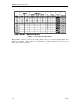
GASBOY Series 70 & 1820 Table 1-1. Series 70 and 1820 Features Stripped-down versions of Series 70 pumps, which mount on customer-supplied piping and fittings, are available. Model 72X has no attachments or register, Model 73 has a hose and nozzle, but no meter or register.
Section 2 INSTALLATION INSTALLATION PRECAUTIONS All tanks and installations must conform with all building/fire codes, all Federal, State, and Local codes, National Electrical Code, (NFPA 70), NFPA 30, Automotive and Marine Service Station Code (NFPA 30A) and NFPA 395 codes and regulations. Plan your installation carefully. Dispensing troubles, which seem to be pump-related, are frequently traced to faulty installation.
GASBOY Series 70 & 1820 15. DO NOT use gaskets on covers of explosion-proof type boxes. The sealing compound found around wires at all junction box entrances is a requirement of the National Electrical Code and should not be disturbed. Tighten junction box covers before replacing panels. 16. DO NOT use knock-out boxes or flexible conduit for installing this unit. All power and lighting wires should be run in threaded, rigid, metal conduit.
Installation PUMP DIMENSIONS - SERIES 70, MODEL 1820 Pump diagrams shown are for Model 1820. Pump dimensions are the same for all Series 70 pumps. PUMP DIMENSIONS - MODEL 1820R Pump diagrams shown are for Model 1820R. Pump dimensions are the same for these Model 1820 pumps: 1820R, 1820RSS, 1820RC, 1820RCSS.
GASBOY Series 70 & 1820 INSTALLATION INSTRUCTIONS Cabinet Removal for Installation or Service (Series 1820 Only) - Rounded Cabinet 1. Remove two screws, one on each side of the cabinet. 2. Pull front panel assembly forward at bottom. As it clears the pumping unit, lift up to remove. 3. To replace front panel, engage pins at top in matching holes in rear panel. With front panel assembly tilted back, pins may be seen through dial opening. Front panel assembly will now drop back into position. 4.
Installation Direct Mount on Underground Tanks 1. Screw 2" coupling onto 2" standard pipe. 2. Screw 2" standard pipe into 2" tank flange. Apply compound to threads at bottom of base to prevent surface water from entering the tank. 3. Screw 1" suction pipe into install-a-socket. Suction pipe should be long enough to allow 3" clearance from bottom of tank. Apply gasoline-resistant pipe compound to male threads. 4. Lower 1" suction pipe through 2" standard pipe into tank.
GASBOY Series 70 & 1820 Direct Mount on Aboveground Tank Aboveground tanks require both a pressure/vacuum vent and an emergency vent. The pressure/vacuum vent reduces losses due to evaporation and is an air quality control measure. The emergency vent provides a relief from the pressure resulting from heating and boiling of the tank contents during a fire situation. Both vents must be properly sized for a given tank. 1. Screw 1" suction pipe into install-a-socket.
Installation Pedestal Mount Pump 1. 2. 3. 4. 5. 6. 7. 8. Screw 2" coupling onto threaded end of 2" standard pipe. Slide cast iron pedestal base up over the unthreaded end of 2" standard pipe. Screw 1" suction pipe into install-a-socket. Suction pipe should be long enough to allow 3" clearance from bottom of tank. Apply gasoline-resistant pipe compound to male threads. Insert 1" suction pipe into 2" pipe and screw install-a-socket into coupling on end of 2" pipe.
GASBOY Series 70 & 1820 Wall Mount The optional wall mount kit can be used with any Series 70 or 1820 pump to be located remote from the tank. The wall mount kit consists of a wall mounting bracket, pump mounting flange, and hardware to attach the flange to the bracket. Hardware to attach the bracket to the wall is not included. 1. 2. 3. 4. Fasten mounting bracket to wall using appropriate 3/8" fasteners (customer supplied). Screw mounting flange to pump inlet.
Installation Vacuum Breaker The vacuum breaker tubing kit can be used with any Series 70 or 1820 pump. The vacuum breaker is used to break a siphon should the nozzle drop below the fluid level in the tank while the pump is stuck in the open position. A threaded vacuum breaker, P/N 066570 is shipped installed in the pump. GASBOY recommends that the vacuum breaker be tubed back to the tank. The illustration below shows two methods for installing tubing for the vacuum breaker.
GASBOY Series 70 & 1820 NOTE: Tubing can be piped to any available opening on top of tank. Use reducer bushings as required. Testing the Vacuum Breaker 1. Charge tubing completely with fluid. 2. Turn on pump and run for several minutes to purge any air from the system. 3. Turn off pump. 4. With nozzle at ground level and discharging into a container, open nozzle. A small quantity of fluid (several cups) should drain and then stop.
Section 3 WIRING WIRING PRECAUTIONS The quality of the electrical installation is a major factor in maintaining proper safety levels and providing trouble-free operation of your GASBOY pump. To assure a quality installation, follow these rules: 1. Have the pump installed by a competent installer/electrician. 2.
GASBOY Series 70 & 1820 GROUNDING To ensure proper operation of the equipment and provide the necessary safety factors, this unit must be grounded. A ground wire (preferably green) must be connected between the unit's AC junction box ground lug and the main electrical service panel. One (1) earth ground connection is required per unit. The ground rod is to be a solid, corrosion-resistant conductor and must be installed at the main electrical panel in accordance with the National Electrical Code.
Wiring PULSER WIRING An optional pulser (available on the Series 1820R only) is used when external monitoring of the dispensing unit operation is desired. The pulser transmits one electrical signal (pulse) for each predetermined amount of fuel dispensed. Reed 10:1 pulsers operating with DC voltages are used. Pulser wiring must be 18AWG and installed in metal conduit separate from all AC wiring. It cannot share a common junction box, wiring trough or conduit with any AC wiring.
GASBOY Series 70 & 1820 PUMP WIRING DIAGRAMS 115VAC Pumps Series 70 and 1820 (left) and Series 1820R (right) 230VAC Pumps Series 70 and 1820 (left) and Series 1820R (right) NOTE FOR 230V MOTORS: Some motors may contain different wire colors than those shown. In this case, Hot is Black, Neutral is White and Aux AC Control is Brown. 1. 2. 3. 4.
Section 4 STARTUP AND OPERATION PRE-STARTUP CHECKLIST The information below should be reviewed to help verify the proper installation of your GASBOY pump. If the installation does not meet criteria listed, as well as any Federal, State, and Local codes and requirements, correct the problem before powering on the unit. 1. The unit must be properly secured. 2. All plumbing must be complete and tight. All liquid-carrying lines must be checked for leaks. 3.
GASBOY Series 70 & 1820 POST-STARTUP TESTS Voltage The incoming voltage to the pump should be checked and any reading not within 10% of rated voltage should be corrected before testing is continued. When dealing with suction pumps it is good practice to take voltage readings while the suction pump is operating on bypass (turned on but not dispensing product) and also while making a delivery.
Start-Up and Operation Clean the strainer immediately after the pump has been installed and tested, and again after a few hundred gallons have been delivered. Thereafter, once every six months, or as required. The procedure for cleaning the stainer can be found in the Maintenance and Troubleshooting section. DAILY OPERATION 1. To begin fueling, remove the nozzle from the boot and turn on the pump handle. 2. If your model has an automatic reset, the register resets to zeros.
Section 5 MAINTENANCE AND TROUBLESHOOTING MAINTAINING TROUBLE-FREE OPERATION Operating your pump with reasonable care will prolong its life and provide better service. GASBOY pumps are designed and built to provide years of uninterrupted service; however, certain parts of a pump are bound to wear. To keep your pump running at maximum efficiency, GASBOY recommends a periodic inspection at least twice a year. ● Remove Water from Tank. After every fill-up, check your tanks for water.
GASBOY Series 70 & 1820 WHEN YOUR PUMP NEEDS SERVICE When your pump needs service, follow these guidelines: ● Procedures requiring disassembly of portions of the pump should be performed by competent service personnel. GASBOY has a distributor network which services fuel dispensing equipment in every part of the country. ● Turn off all power to the pump to reduce the risk of electrical shock when servicing (including changing of fuel filters or strainers).
Service and Troubleshooting TROUBLESHOOTING If problems are encountered in operation of the pump, follow the procedures below in an attempt to isolate the problem. When the problem is detected, follow the procedures for disassembly of the pump. Pump Won't Start ✓ ✓ ✓ ✓ ✓ ! Is the breaker at the panel turned on? Is the Aux AC Control wire capped or connected to a solenoid valve or fuel management system? Is there power at pump? Check at junction box.
GASBOY Series 70 & 1820 Pump delivers product but won't register. ✓ ✓ Is main totalizer recording? If yes, problem is in register assembly. Check to be sure the lever on the side of the register is returning back to the record position. If the main totalizer is not working, the problem is a broken or jammed measuring chamber. Pump delivery is slow. ✓ ✓ ✓ ✓ Check for dirty strainer. If pump has a filter, change filter. An automatic nozzle will reduce flow rate about 25%.
Service and Troubleshooting DISASSEMBLY OF PUMP NOTE: Numbers in parentheses correspond to the numbers shown on the parts illustration and parts list in Section 6 labeled Direct Drive Motor-Pump Assembly. When the front panel is removed, all the working parts of the pump are accessible under clearly marked cover plates. Since pump may contain product, be prepared to catch product in an appropriate container when removing any cover. Remove pump cover screws and remove cover plate (1) and square ring (2).
GASBOY Series 70 & 1820 1860 3-WHEEL REGISTER SERVICE AND MAINTENANCE NOTE: Numbers in parentheses correspond to the numbers shown on the parts illustration and parts list in Section 6 labeled 1860 3-Wheel Meter-Register. To service or replace parts in the disc register, remove the self-tapping screws and lift off the front panel assembly. With the register now exposed, remove three screws with fiber washers (28 & 29). Lift off dial glass (30), and dial mask (32).
Service and Troubleshooting 3. Hook spring (25) over post so that hook lies flat against rear of housing. 4. Make sure lower arm and overthrow stop pawl (19) fits into slot in reset lever. 5. To time the register for zero reset, pry apart the center wheel and (13 and 16) and place 16 on middle post with two red marks pointing toward the other two posts. Line up the red arrows on the lefthand and righthand wheels with marks on the center wheel as shown in drawing.
GASBOY Series 70 & 1820 Replacing Bearing and Seal Assembly (Item 26, New Style) To replace the bearing and shaft seal assembly (26), or service the gear train on back of register housing (18), remove housing from meter by taking out four screws. NOTE: The meter housing will be full of liquid so some means should be available to catch what drains from the case and lines. To remove gears (22-25), remove three retaining rings (20) and drive key (21).
Section 6 PARTS Using part numbers when ordering will expedite your order and reduce the possibility of the wrong parts being shipped. When ordering replacement parts, be sure to give the complete name and part number as shown in the appropriate parts lists. Procedures requiring disassembly of portions of the pump should be performed by competent service personnel. Do not depend upon the repair service of a general mechanic unless he is thoroughly familiar with the mechanism.
GASBOY Series 70 & 1820 SERIES 70 ASSEMBLY 6-2 9312
Parts SERIES 70 ASSEMBLY Item 1 2 3 4 5 6 7 8 9 10 11 12 13 14 15 16 17 Part No. Description 044089 003597 024934 052000 027055 003542 003544 052105 068020 039085 000325 029410 053900 030539 038471 034121 066534 Pump Assembly (See Direct Drive Motor Parts List) 3/4" X 6-7/8" Pipe Nipple Flanged Inlet, 72S Elbow, 72X & 73 Screw Gasket 3/4" Horiz. Dschg for Vacuum Breaker 1" Horiz.
GASBOY Series 70 & 1820 SERIES 1820 ASSEMBLY 6-4 9312
Parts SERIES 1820 ASSEMBLY Item Part No. Description Item Part No.
GASBOY Series 70 & 1820 DIRECT DRIVE MOTOR-PUMP ASSEMBLY 6-6 0259
Parts DIRECT DRIVE MOTOR-PUMP ASSEMBLY Item Part No.
GASBOY Series 70 & 1820 INSTALLATION PARTS Item Part No.
Parts 1860 AND 4860 METER-REGISTER REGISTER ASSEMBLIES Item Part No. Description 1 2 3 4 5 012790 051835 049075 025851 019016 Meter Body Meter Body Screw O-Ring Screw Meas. Chamber Assy. (sold as assembly only; includes items 6-9) Bronze Meas. Chamber Meas. Chamber Top Measuring Disc Baffle Meas.
GASBOY Series 70 & 1820 1860 3-WHEEL METER REGISTER (FOR MODEL 1820) 6-10 9312
Parts 1860 3-WHEEL METER REGISTER (FOR MODEL 1820) 035634 US Measure 035640 Liter Measure, 1/10 036296 Liter Measure, Full 035638 Imperial Measure Item Part No. Item 1 2 3 052840 028615 065305 Description Screw Totalizer Drive Gear Totalizer Assembly (items 4-7. Not sold separately.
GASBOY Series 70 & 1820 4860 4-WHEEL REGISTER (FOR MODEL 72S AND SERIES 1820R) 6-12 9312
Parts 4860 4-WHEEL REGISTER (FOR MODEL 72S AND SERIES 1820R) 036341 036343 036345 U.S. Measure, 72S Liter Measure, 72S Imperial Measure, 72S 036357 036361 036353 036373 US Measure, 1820R Liter Measure, 1820R US Measure, Ext. Shaft, 1820R Liter Measure, Ext. Shaft, 1820R Item Part No.
GASBOY Series 70 & 1820 6-14 9312
Parts MODEL 1820 REGISTER SETBACK AND SWITCH LINKAGE ASSEMBLY PARTS LIST Item Part No.
GASBOY Series 70 & 1820 6-16 9312
Parts MODEL 1820R PARTS LIST Item Part No. Description 1 022194 022971 012267 041384 041383 021374 017931 003835 022193 022970 022988 022979 040754 040811 068080 068281 051072 026575 053516 017578 033748 063209 052314 Cover-1820R, CRS Cover-1820R, SS Bezel Panel Assy.-Right, CRS Panel Assy.
GASBOY Series 70 & 1820 1820R PULSER AND JUNCTION BOX ASSEMBLIES Item Part No.
GW98- 4/13/98 Rev. 1 WARRANTY General Statements: • Gasboy International, Inc. warrants all new equipment manufactured by Gasboy against defective material and/or workmanship, for the warranty period specified below, when the equipment is installed in accordance with specifications prepared by Gasboy.