Item # 1000 772 228 Model # TF291204 USE AND CARE GUIDE 80-GALLON STATIONARY AIR COMPRESSOR Questions, problems, missing parts? Before returning to the store, call Husky Customer Service 8 a.m. - 6 p.m., EST, Monday - Friday 1-888-43-HUSKY HUSKYTOOLS.COM THANK YOU We appreciate the trust and confidence you have placed in Husky through the purchase of this air compressor. We strive to continually create quality products designed to enhance your home.
Table of Contents Safety Information . . . . . . . . . . . . . . . . . . . . . . . . . . . . . . . . . . 2 California Proposition 65 . . . . . . . . . . . . . . . . . . . . . . . . . . . . 2 General Safety . . . . . . . . . . . . . . . . . . . . . . . . . . . . . . . . . . . . 3 Work Area Safety . . . . . . . . . . . . . . . . . . . . . . . . . . . . . . . . . . 4 Personal Safety . . . . . . . . . . . . . . . . . . . . . . . . . . . . . . . . . . . 5 Electrical Safety . . . . . . . . . . . . . . . . . . . .
Safety Information (continued) GENERAL SAFETY DANGER: Breathable Air Warning: This compressor/pump is NOT equipped and should NOT be used “as is” to supply breathing quality air. For any application of air for human consumption, you must fit the air compressor/pump with suitable in-line safety and alarm equipment.
Safety Information (continued) WORK AREA SAFETY WARNING: Motors, electrical equipment, and controls can cause electrical arcs that will ignite a flammable gas or vapor. Never operate or repair in or near a flammable gas or vapor. Never store flammable liquids or gases in the vicinity of the compressor. WARNING: An ASME code safety relief valve with a setting no higher than the maximum allowable working pressure (MAWP) MUST be installed in the tank for this compressor.
Safety Information (continued) PERSONAL SAFETY WARNING: Never operate the compressor without a beltguard. This unit can start automatically without warning. Personal injury or property damage could occur from contact with moving parts. CAUTION: Compressor parts may be hot even if the unit is stopped. 1. Wear safety glasses and use hearing protection when operating the unit. 2. Do not stand on or use the unit as a handhold. 3.
Warranty LIMITED TWO-YEAR WARRANTY WHAT IS COVERED From the date of purchase, parts and labor are covered to remedy substantial defects due to material and workmanship during the first year of ownership with the exceptions noted below. From the date of purchase, parts only are covered to remedy substantial defects due to material and workmanship during the second year of coverage with exceptions noted below. This warranty applies only to the original retail purchaser and may not be transferred.
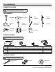
Pre-Installation PLANNING INSTALLATION WARNING: Disconnect, tag, and lock out the power source before attempting to install or relocate the compressor. TOOLS REQUIRED Claw hammer Safety goggles Phillips screwdriver Flat blade screwdriver Measuring tape Adjustable wrenches (2) Ratchet and 1/2 in. socket Pipe wrench Hammer drill and masonry bit Voltage meter Work gloves HARDWARE INCLUDED NOTE: Hardware not shown to actual size.
Pre-Installation PACKAGE CONTENTS B A Part Description Quantity A Air Compressor Unit 1 B Air Filter Assembly 1 8
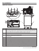
Pre-Installation COMPRESSOR COMPONENTS I H K J G C E M B A F F M L Side View Part A B C Description Pressure Switch - The compressor shuts off automatically when the tank pressure reaches the maximum preset pressure. After air is used from the tank and drops to a preset low level, the pressure switch signals the magnetic starter to turn the motor back on. When the motor turns off, you will hear air leaking out of the pressure switch unloader valve for a short time.
Pre-Installation (continued) SPECIFICATIONS Horsepower (HP) 7.5 Tank Outlet Size 3/4 NPT Number of Cylinders 2 Oil Capacity approximately 2 quarts Voltage 230 / 240 Volts, 31 Amps Length 29 in. 60 Hz, 1 Phase Width 33 in. Air Delivery @ 175 psi 22.2 SCFM Height 77 in. Air Delivery @ 90 psi 23.7 SCFM Weight 540 lbs. Max.
Installation - Mounting 1 Preparing for installation WARNING: Disconnect, tag, and lock out the power source, and then release all pressure from the system before attempting to install, service, relocate, or perform any maintenance. WARNING: This compressor is extremely top heavy. Enlist additional help to remove it from the shipping skid. CAUTION: Never use the shipping skid for mounting the compressor. IMPORTANT: Provide a minimum clearance of 18 in.
Installation - Mounting (continued) 2 3 Drilling the mounting holes Inserting the mounting bolts □ Insert the mounting bolts into the drilled holes. WARNING: This compressor is extremely top heavy. The unit must be bolted to the floor with isolation pads before operating to prevent equipment damage, injury, or death. □ Place a washer on each bolt. Thread a nut onto each bolt until the top of the nuts and bolts are flush.
Installation - Electrical 1 Preparing for installation 1 DANGER: Improperly grounded motors are shock hazards. Make sure all the equipment is properly grounded. WARNING: All wiring and electrical connections must be performed by a qualified electrician familiar with industrial motor controls. Installations must be in accordance with local and national codes.
Installation - Electrical (continued) 2 Preparing the magnetic starter □ Remove the magnetic starter cover by loosening the screw (1), as shown. Use a Phillips screwdriver. □ Lift the cover upwards from the bottom and off the base. □ Set the cover aside until wiring is completed. □ Familiarize yourself with these internal components of the magnetic starter.
Installation - Electrical (continued) 3 Making the electrical connections □ Use a blunt tool and hammer to carefully tap out the stamped cover (1) at the top of the magnetic starter box (2). 1 □ Loosen the ground screw (3). Loosen the terminal screws (4). □ Install the strain relief (5) on the magnetic starter (2). Do not tighten the screws (6) or nut (7) of the strain relief (5) on the power cord until wiring is complete.
Installation - Electrical (continued) 4 Securing the strain relief 2 1 □ Tighten the strain relief nut (1). Place a flathead screwdriver into the raised notch, and tap the screwdriver with a hammer until tight. □ Tighten the strain relief screws (2) to hold the power cord securely. 5 Reinstalling the magnetic starter cover □ Replace the magnetic starter cover. □ Tighten the magnetic cover screw (1) with a Phillips screwdriver. Follow the break-in procedure from the owner’s manual.
Assembly 1 Assembling the air compressor unit B WARNING: Never use plastic (PVC) pipe for compressed air. Serious injury or death could result. WARNING: Never install a shut-off valve between the compressor pump and the tank. Personal injury and / or equipment damage may occur. Never use reducers in discharge piping. NOTE: Do not overtighten. Over the life of the unit, you will clean or replace the filter as needed. This air compressor unit can be installed as part of an air distribution system.
Operation 1 Preparing for use 1 CAUTION: Check for proper oil level before operating! 2 NOTE: The pump oil level is full (1) as shown. NOTE: Use SAE 30 industrial grade air compressor oil or full synthetic motor oil like Mobil 1® 10W30. NOTE: Do not exceed the maximum oil capacity of approximately 2 qts. NOTE: Do not use regular automotive oil. Additives in regular motor oil can cause valve deposits and reduce pump life.
Operation (continued) ON/OFF CYCLING OF THE COMPRESSOR The air compressor unit (A) is designed to cycle on and off. When the shut-off (preset “cut-out”) pressure is reached, the compressor automatically shuts off. When air is depleted from the tank by use of a tire chuck, tool, etc., the compressor will restart automatically at its preset “cut-in” pressure. When a tool is in use, the compressor will cycle on and off automatically as needed to maintain air pressure in the tank.
Maintenance GENERAL MAINTENACE All repairs should be performed by an authorized service representative. WARNING: Disconnect, tag, and lock out the power source, and then release all pressure from the system before attempting to install, service, relocate, or perform any maintenance. 1 Checking and changing the oil Maintain the proper oil level by checking the oil sight glass (1) daily. Change the oil in the pump every 3 months. Use the following procedure to change (or add) oil.
Maintenance (continued) 4 5 Checking the belt □ Remove the four caps (1) and four flange nuts (2). Removing the belt □ Remove the front beltguard (3). □ Loosen (but do not remove) the four bolts (1) holding the motor in place. □ Pull the front beltguard (3) away from the air compressor unit (A). □ Shift the motor towards the pump. The belt should be slack and easily removed.
Maintenance (continued) 7 Reseting the thermal overload Allow the air compressor unit (A) to cool down after thermal overload of the magnetic starter is tripped. □ Disconnect, tag, and lock out the power source for the air compressor unit (A). □ Push the external reset switch (1). The internal overload switch (2) will be pushed back into place and return contact for the electrical current. □ Return power to the air compressor unit (A).
Maintenance (continued) 8 Checking the air filter 4 3 2 1 □ Remove the nut (1). □ Remove the air filter cover (2) from the air filter base (4). □ Remove and inspect the air filter element (3). □ If the air filter element is dirty, replace it. Install a new filter element. If the air filter element is clean, reinstall it. □ Reattach the air filter cover (2). □ Reattach the nut (1). Do not overtighten the nut as this maintenance process will be repeated regularly.
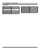
Troubleshooting Problem Possible Cause Solution The discharge pressure is low. □ The air demand exceeds the pump capacity. □ Reduce the air demand or use a compressor with more capacity. □ The air intake is restricted. □ Clean or replace the air filter element. □ There are air leaks in the fittings, tubing on the compressor, or the plumbing outside the unit. □ Listen for escaping air. Apply soap solution to all fittings and connections. Bubbles will appear at points of leakage.
Troubleshooting (continued) Problem Possible Cause The motor hums and runs □ The voltage is low. slowly, or the motor does not run at all. □ There are too many devices on the same circuit. Solution □ Check incoming voltage. It should be approximately 240 volts. The motor will not run properly on 208 volts. Low voltage could be due to wires (from electrical source to compressor) being too small in diameter and / or too long. Have a qualified electrician check these conditions and make repairs as needed.
Troubleshooting (continued) Problem Possible Cause The motor hums and runs □ The voltage supplied to the air compressor unit is low or not slowly or not at all. present. □ Check the incoming voltage with a voltmeter. Check the overload relay in magnetic starter or the reset switch on the motor. If the overload or the reset switch trips repeatedly, find and correct the cause. □ The motor winding is shorted or open. □ Replace the motor. □ The check valve or the unloader valve is malfunctioning.
Notes ___________________________________________________________________________________________________________ ___________________________________________________________________________________________________________ ___________________________________________________________________________________________________________ ___________________________________________________________________________________________________________ __________________________________________________________________________
Service Parts - Compressor MODEL TF291204 48 46 15 49 31 44 47 5 16 17 12 2 10 32 3 22 19 5 24 26 25 35 27 45 4 14 19 42 6 21 39 40 37 20 1 13 33 34 38 41 37 36 42 7 40 43 9 11 10 37 34 50 23 28 8 30 18 29 28
Service Parts - Compressor (continued) Part 1 2 Description Part Number Qty Hex head cap screw, 7/16 - 14 x 1-1/2 ST070645AV 4 Part Description Part Number Qty 36 Plug ST187200AV 1 37 External tooth lock washer ST072608AV 4 38 5/16 Flange head bolt ST187300AV 1 39 Push connect ST119704AV 2 40 Tube, pressure switch to tank WL005900AV 1 41 Tube, pressure switch to control panel Hex head cap screw, 3/8 - 16 x 1-1/4 ST070638AV 4 3 Washer, 7/16 ST070916AV 8 4 Washer, 3/8
Service Parts - Pump MODEL XP7101 26 28 25 27 41 24 22 37 38 31 30 29 39 15 32 40 42 36 35 43 19 33 23 34 21 7 8 44 2 45 18 17 13 14 1 11 3 4 5 6 9 10 30 12 16 6 19 20
Service Parts - Pump (continued) Part Description Part Number Qty Part Description Part Number 1 Oil seal 1 2 Ball bearing FP070042AV ◆✖ ● 2 3 Cooler bracket 4 Washer -✤ 5 Bracket fixing bolt ✤ 1 6 Crankcase Fill plug -✖ 1 7 1 8 Fill plug o-ring ✖✖ 9 Drain plug 10 11 Qty 32 Low pressure piston pin ■ 1 33 High pressure piston pin ● 1 34 High pressure piston ● 1 1 35 High pressure oil control ring ◆ 1 1 36 High pressure compression ring ◆ 3 37 Cylinde
Questions, problems, missing parts? Before returning to the store, call Husky Customer Service 8 a.m.-6 p.m., EST, Monday-Friday 1-888-43-HUSKY HUSKYTOOLS.COM Retain this manual for future use.