Item # 1000 710 098 Model # VT631404 USE AND CARE GUIDE 60-GALLON STATIONARY AIR COMPRESSOR Questions, problems, missing parts? Before returning to the store, call Husky Customer Service 8 a.m. - 6 p.m., EST, Monday - Friday 1-888-43-HUSKY HUSKYTOOLS.COM THANK YOU We appreciate the trust and confidence you have placed in Husky through the purchase of this air compressor. We strive to continually create quality products designed to enhance your home.
Table of Contents Safety Information . . . . . . . . . . . . . . . . . . . . . . . . . . . . . . . . . . 2 California Proposition 65 . . . . . . . . . . . . . . . . . . . . . . . . . . . . 2 General Safety . . . . . . . . . . . . . . . . . . . . . . . . . . . . . . . . . . . . 3 Work Area Safety . . . . . . . . . . . . . . . . . . . . . . . . . . . . . . . . . . 4 Personal Safety . . . . . . . . . . . . . . . . . . . . . . . . . . . . . . . . . . . 5 Electrical Safety . . . . . . . . . . . . . . . . . . . .
Safety Information (continued) GENERAL SAFETY DANGER: Breathable Air Warning: This compressor/pump is NOT equipped and should NOT be used “as is” to supply breathing quality air. For any application of air for human consumption, you must fit the air compressor/pump with suitable in-line safety and alarm equipment.
Safety Information (continued) WORK AREA SAFETY WARNING: Motors, electrical equipment, and controls can cause electrical arcs that will ignite a flammable gas or vapor. Never operate or repair in or near a flammable gas or vapor. Never store flammable liquids or gases in the vicinity of the compressor. WARNING: An ASME code safety relief valve with a setting no higher than the maximum allowable working pressure (MAWP) MUST be installed in the tank for this compressor.
Safety Information (continued) PERSONAL SAFETY WARNING: Never operate the compressor without a beltguard. This unit can start automatically without warning. Personal injury or property damage could occur from contact with moving parts. CAUTION: Compressor parts may be hot even if the unit is stopped. 1. Wear safety glasses and use hearing protection when operating the unit. 2. Do not stand on or use the unit as a handhold. 3.
Warranty LIMITED TWO-YEAR WARRANTY WHAT IS COVERED From the date of purchase, parts and labor are covered to remedy substantial defects due to material and workmanship during the first year of ownership with the exceptions noted below. From the date of purchase, parts only are covered to remedy substantial defects due to material and workmanship during the second year of coverage with exceptions noted below. This warranty applies only to the original retail purchaser and may not be transferred.
Pre-Installation PLANNING INSTALLATION WARNING: Disconnect, tag, and lock out the power source before attempting to install or relocate the compressor. IMPORTANT: This compressor is not intended for outdoor installation. It is extremely important to install the compressor in a clean, well ventilated area where the surrounding air temperature will not be more than 100°F. Provide a minimum clearance of 18 in.
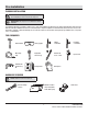
Pre-Installation PACKAGE CONTENTS B A Part Description Quantity A Air Compressor Unit 1 B Air Filter Assembly 1 8
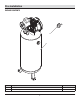
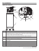
Pre-Installation COMPRESSOR COMPONENTS C H E I D G B A F Part A B C Description Pressure Switch (AUTO / OFF Switch) - In the AUTO position, the compressor shuts off automatically when the tank pressure reaches the maximum preset pressure. After air is used from the tank and drops to a preset low level, the pressure switch automatically turns the motor back on. In the OFF position, the compressor will not operate.
Pre-Installation (continued) SPECIFICATIONS Horsepower (HP) 3.2 Tank Outlet Size 3/4 NPT Number of Cylinders 2 Oil Capacity approximately 8.5 ounces Voltage 230 / 240 Volts, 15 Amps Length 20 in. 60 Hz, 1 Phase Width 20 in. Air Delivery @ 90 psi 10.2 SCFM Height 66.5 in. Air Delivery @ 40 psi 11.5 SCFM Shipping Weight 255 lbs. Max.
Installation - Mounting 1 Preparing for installation WARNING: Disconnect, tag, and lock out the power source, and then release all pressure from the system before attempting to install, service, relocate, or perform any maintenance. WARNING: This compressor is extremely top heavy. Enlist additional help to remove it from the shipping skid. CAUTION: Never use the shipping skid for mounting the compressor. A IMPORTANT: Provide a minimum clearance of 18 in.
Installation - Mounting (continued) 2 Drilling the mounting holes 3 Inserting the mounting bolts □ Insert the mounting bolts into the drilled holes. WARNING: This compressor is extremely top heavy. The unit must be bolted to the floor with isolation pads before operating to prevent equipment damage, injury, or death. □ Place a washer on each bolt. Thread a nut onto each bolt until the top of the nuts and bolts are flush.
Installation - Electrical 1 Preparing for installation DANGER: Improperly grounded motors are shock hazards. Make sure all the equipment is properly grounded. WARNING: All wiring and electrical connections must be performed by a qualified electrician familiar with industrial motor controls. Installations must be in accordance with local and national codes.
Installation - Electrical (continued) 2 Preparing the pressure switch □ Remove the pressure switch cover by loosening the screw (1), as shown. Use a Phillips screwdriver. 1 □ Set the cover aside until wiring is completed. □ Familiarize yourself with these internal components of the pressure switch. □ Refer to the illustration below to identify the motor terminal (2), line terminal (3), ground screw (4), and ground line (5).
Installation - Electrical (continued) 4 Securing the strain relief □ Tighten the strain relief nut (1). Place a flathead screwdriver into the raised notch, and tap the screwdriver with a hammer until tight. □ Tighten the strain relief screws (2) to hold the power cord securely. 5 2 Reinstalling the pressure switch cover 1 □ Replace the pressure switch cover. The knob must be in the same position as when removed to sit correctly in place.
Assembly 1 Assembling the air compressor unit WARNING: Never use plastic (PVC) pipe for compressed air. Serious injury or death could result. B WARNING: Never install a shut-off valve between the compressor pump and the tank. Personal injury and / or equipment damage may occur. Never use reducers in discharge piping. NOTE: Do not overtighten. Over the life of the unit, you will clean or replace the filter as needed. This air compressor unit can be installed as part of an air distribution system.
Operation 1 Preparing for use CAUTION: Check for proper oil level before operating! 1 NOTE: The pump oil level is full (1) as shown. 2 NOTE: Use SAE 30 industrial grade air compressor oil or full synthetic motor oil like Mobil 1® 10W30. NOTE: Do not exceed the maximum oil capacity of approximately 8.5 ounces. NOTE: Do not use regular automotive oil. Additives in regular motor oil can cause valve deposits and reduce pump life.
Operation (continued) ON/OFF CYCLING OF THE COMPRESSOR The air compressor unit (A) is designed to cycle on and off. With the pressure switch knob in the AUTO position, the compressor pumps air into the tank. When the shut-off (preset “cut-out”) pressure is reached, the compressor automatically shuts off. If the compressor is left in the AUTO position and air is depleted from the tank by use of a tire chuck, tool, etc., the compressor will restart automatically at its preset “cut-in” pressure.
Maintenance GENERAL MAINTENACE All repairs should be performed by an authorized service representative. WARNING: Disconnect, tag, and lock out the power source, and then release all pressure from the system before attempting to install, service, relocate, or perform any maintenance. 1 Checking and changing the oil Maintain the proper oil level by checking the oil sight glass (1) daily. Change the oil in the pump every 3 months. Use the following procedure to change (or add) oil.
Maintenance (continued) 4 5 Checking the belt □ Remove the beltguard screw (1). Removing the belt □ Loosen (but do not remove) the four bolts (1) holding the motor in place. □ Remove the front beltguard (2). The beltguards are held together by pressure snap-latches (3). Wedge a flathead screwdriver between the beltguards at the snap-latches. □ Shift the motor towards the pump. The belt should be slack and easily removed. □ Wedge a screwdriver at the other snap-latch junctions.
Maintenance (continued) 7 Checking the air filter 5 4 3 2 1 □ Remove the nut (1) and the washer (2). □ Remove the air filter cover (3) from the air filter base (5). □ Remove and inspect the air filter element (4). □ If the air filter element is dirty, replace it. Install a new filter element. If the air filter element is clean, reinstall it. □ Reattach the air filter cover (3). □ Reattach the washer (2) and the nut (1).
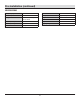
Troubleshooting Problem Possible Cause Solution The discharge pressure is low. □ The air demand exceeds the pump capacity. □ Reduce the air demand or use a compressor with more capacity. □ The air intake is restricted. □ Clean or replace the air filter element. □ There are air leaks in the fittings, tubing on the compressor, or the plumbing outside the unit. □ Listen for escaping air. Apply soap solution to all fittings and connections. Bubbles will appear at points of leakage.
Troubleshooting (continued) Problem Possible Cause The motor hums and runs □ The voltage is low. slowly, or the motor does not run at all. □ There are too many devices on the same circuit. Solution □ Check incoming voltage. It should be approximately 240 volts. The motor will not run properly on 208 volts. Low voltage could be due to wires (from electrical source to compressor) being too small in diameter and / or too long. Have a qualified electrician check these conditions and make repairs as needed.
Service Parts - Compressor MODEL VT631404 32 29 30 25 31 28 27 33 4 3 17 23 5 26 10 19 24 21 7 22 34 11 12 2 24
Service Parts - Compressor (continued) Part Description Part Number Quantity 1 Tank AR060300CG 1 2 Drain valve D-1403 1 3 Electric motor MC019000SJ 1 4 Key KE000900AV 1 5 Hex head screw ST016000AV 4 6 Washer ST011200AV 4 7 Locknut ST146001AV 4 8 Nipple HF002401AV 1 9 Pressure switch CW209300AV 1 10 Motor cord EC012800AV 1 11 ASME Safety valve V-215105AV 1 12 Plug ST022500AV 1 13 Gauge GA031900AV 1 14 Unloader valve CW210001AV 1 15 Check valve CV2
Service Parts - Pump MODEL VT472200AJ 14 15 18 13 12 16 17 19 11 20 21 22 10 9 7 23 8 24 26 6 25 5 4 2 3 2 27 1 26 28
Service Parts - Pump (continued) Part Description Part Number Quantity 1 Crankcase VT040300AV 1 2 Ball bearing ST084202AV ▲ 2 3 Crankshaft ▲ 1 4 O-ring ■● 1 5 Oil seal ST129700AV ■ ● 1 6 Bearing cap ● 1 7 Cap screw, M6 - 1.
Questions, problems, missing parts? Before returning to the store, call Husky Customer Service 8 a.m.-6 p.m., EST, Monday-Friday 1-888-43-HUSKY HUSKYTOOLS.COM Retain this manual for future use.