07002 LGT2554 Owner's Manual "This machine is approved by the EPA for E10 (10% ethanol) and lower fuel only. Do not use any fuel >E10 in this machine.
SAFETY RULES Safe Operation Practices for Ride-On Mowers DANGER: THIS CUTTING MACHINE IS CAPABLE OF AMPUTATING HANDS AND FEET AND THROWING OBJECTS. FAILURE TO OBSERVE THE FOLLOWING SAFETY INSTRUCTIONS COULD RESULT IN SERIOUS INJURY OR DEATH. • WARNING: In order to prevent accidental starting when setting up, transporting, adjusting or making repairs, always disconnect spark plug wire and place wire where it cannot contact spark plug.
SAFETY RULES Safe Operation Practices for Ride-On Mowers III. CHILDREN Tragic accidents can occur if the operator is not alert to the presence of children. Children are often attracted to the machine and the mowing activity. Never assume that children will remain where you last saw them. • Keep children out of the mowing area and in the watchful care of a responsible adult other than the operator. • Be alert and turn machine off if a child enters the area.
PRODUCT SPECIFICATIONS CUSTOMER RESPONSIBILITIES Gasoline Capacity and type: 4 Gallons Unleaded Regular • • Oil Type (API-SG-SL): SAE 10W-30 (above 32°F) SAE 5W-30 (below 32°F) • Oil Capacity: W/ Filter: Spark Plug: Champion RC12YC (Gap: .030") Ground Speed (MPH): Forward: Reverse: Charging System: 15 AMPS @ 3600 RPM Battery: AMP/HR: MIN. CCA: Case Size: Blade Bolt Torque: 45-55 FT. LBS. 64 oz Read and observe the safety rules.
UNASSEMBLED PARTS Mower Mower Front Wheel (2) Rear Lift Link Assemblies (5) 1-3/16 O.D. Washers (1) Shoulder Bolt (1) 1-1/4 O.D. Washer (1) Small Retainer Springs (1) Front Lift Link Assembly (1) 3/8-16 Locknut (1) Wheel (5) Large Retainer Springs (1) Anti-Sway Bar Slope Sheet (1) Oil Drain Tube If Equipped Keys (1) 3/4 O.D.
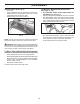
ASSEMBLY ADJUST SEAT (See Fig. 2) • • • TO INSTALL MOWER AND DRIVE BELT (See Figs. 3 - 14) Sit in seat. Lift up adjustment lever (A) and slide seat until a comfortable position is reached which allows you to press clutch/brake pedal all the way down. Release lever to lock seat in position. 1. SET PARKING BRAKE LEVER AND LOWER ATTACHMENT LIFT (See Fig. 3) • Depress clutch/brake pedal all the way down and hold.
ASSEMBLY 4. SLIDE MOWER UNDER TRACTOR (See Fig. 7) • Bring belt forward and check belt for proper routing in all mower pulley grooves. NOTE: Be sure mower side suspension arms (A) are pointing forward before sliding mower under tractor. • Slide mower under tractor until it is centered under tractor. CAUTION: Continuing to press the electric lift switch after the mower deck has reached the minimum or maximum position may result in damage to the electric lift mechanism.
ASSEMBLY ANTI-SWAY BAR (S) LOCATION 7. ATTACH REAR LIFT LINKS (C) (See Fig. 12) • Insert rod end of rear lift link (C) into hole (U) in tractor lift shaft suspension arm and pivot link down to mower. • Lift rear corner of mower and position slot in link assembly over pin on rear mower bracket (D) and secure with large washer and large retainer spring. • Repeat on opposite side of tractor. TRANSAXLE BRACKET (T) LOCATED BETWEEN REAR TIRES E TO HOL END IN ° 0 9 E PL AC U C C. REAR LIFT LINK(S) D.
ASSEMBLY ✓CHECKLIST 9 INSTALL BELT ON ENGINE CLUTCH PULLEY (M) (See Fig. 6 & 14) • Disengage belt tension rod (K) from locking bracket (L). • Install belt onto engine clutch pulley (M). BEFORE YOU OPERATE YOUR NEW TRACTOR, WE WISH TO ASSURE THAT YOU RECEIVE THE BEST PERFORMANCE AND SATISFACTION FROM THIS QUALITY PRODUCT. PLEASE REVIEW THE FOLLOWING CHECKLIST: M ✓ ✓ ✓ ✓ ✓ M.ENGINE CLUTCH PULLEY Fig. 14 ✓ IMPORTANT: Check belt for proper routing in all mower pulley grooves and under mandrel covers.
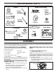
OPERATION These symbols may appear on your tractor or in literature supplied with the product. Learn and understand their meaning.
OPERATION KNOW YOUR TRACTOR READ THIS OWNER'S MANUAL AND SAFETY RULES BEFORE OPERATING YOUR TRACTOR Compare the illustrations with your tractor to familiarize yourself with the locations of various controls and adjustments. Save this manual for future reference. D P H G E N B A F Q J C M Fig. 15 Our tractors conform to the applicable safety standards of the American National Standards Institute.
OPERATION The operation of any tractor can result in foreign objects thrown into the eyes, which can result in severe eye damage. Always wear safety glasses or eye shields while operating your tractor or performing any adjustments or repairs. We recommend standard safety glasses or a wide vision safety mask worn over spectacles. HOW TO USE YOUR TRACTOR NOTE: Failure to move throttle control between half and full speed (fast) position, before stopping, may cause engine to “backfire”.
OPERATION TO ADJUST GAUGE WHEELS (See Fig. 21) TO MOVE FORWARD AND BACKWARD (See Fig. 19) Gauge wheels are properly adjusted when they are slightly off the ground when mower is at the desired cutting height in operating position. Gauge wheels then keep the deck in proper position to help prevent scalping in most terrain conditions. NOTE: Adjust gauge wheels with tractor on a flat level surface. • Adjust mower to desired cutting height (See “TO ADJUST MOWER CUTTING HEIGHT” in this section of manual).
OPERATION REVERSE OPERATION SYSTEM (ROS) TO TRANSPORT (See Fig. 15 and 24) Your tractor is equipped with a Reverse Operation System (ROS). Any attempt by the operator to travel in the reverse direction with the attachment clutch engaged will shut off the engine unless ignition key is placed in the ROS "ON" position. When pushing or towing your tractor, be sure to disengage transmission by placing freewheel control in freewheeling position. Free wheel control is located at the rear drawbar of tractor.
OPERATION TO START ENGINE (See Fig. 15) BEFORE STARTING THE ENGINE When starting the engine for the first time or if the engine has run out of fuel, it will take extra cranking time to move fuel from the tank to the engine. • Be sure freewheel control is in the transmission engaged position. • Sit on seat in operating position, depress clutch/brake pedal and set parking brake. • Place motion control lever in neutral position. • Move attachment clutch to “DISENGAGED” position.
OPERATION MOWING TIPS PURGE TRANSMISSION • CAUTION: Never engage or disengage freewheel lever while the engine is running. • To ensure proper operation and performance, it is recommended that the transmission be purged before operating tractor for the first time. This procedure will remove any trapped air inside the transmission which may have developed during shipping of your tractor.
MAINTENANCE MAINTENANCE SCHEDULE BEFORE EACH USE EVERY 8 HOURS EVERY 25 HOURS EVERY 50 HOURS EVERY 100 HOURS EVERY SEASON BEFORE STORAGE Check Brake Operation T R A C T 0 R Check Tire Pressure Check Operator Presence & ROS Systems Check for Loose Fasteners Check/Replace Mower Blades 3 Lubrication Chart Check Battery Level 4 Clean Battery and Terminals Clean Debris Off Steering Plate Check Transaxle Cooling 5 Check Mower Levelness Check V-Belts Check Engine Oil Level Change Engine Oil (with o
MAINTENANCE TRACTOR BLADE CARE For best results mower blades must be kept sharp. Replace bent or damaged blades. Always observe safety rules when per form ing any maintenance. CAUTION: Use only a replacement blade approved by the manufacturer of your tractor. Using a blade not approved by the manufacturer of your tractor is hazardous, could damage your tractor and void your warranty.
MAINTENANCE TRANSAXLE MAINTENANCE OIL DRAIN VALVE The transmission fan and cooling fins should be kept clean to assure proper cooling. Do not attempt to clean fan or transmission while engine is running or while the transmission is hot. To prevent possible damage to seals, do not use high pressure water or steam to clean transmission. • Inspect cooling fan to be sure fan blades are intact and clean. • Inspect cooling fins for dirt, grass clippings and other materials.
MAINTENANCE DECK WASHOUT PORT (See Fig. 31) IN-LINE FUEL FILTER (See Fig. 29) Your tractor’s deck is equipped with a washout port on its surface as part of its deck wash system. It should be utilized after each use. 1. Drive the tractor to a level, clear spot on your lawn, near enough to a water spigot for your garden hose to reach. IMPORTANT: Make certain the tractor’s discharge chute is directed AWAY from your house, garage, parked cars, etc. Remove bagger chute or mulch cover if attached. 2.
SERVICE AND ADJUSTMENTS WARNING: TO AVOID SERIOUS INJURY, BEFORE PERFORMING ANY SERVICE OR ADJUSTMENTS: • Depress brake pedal fully and set parking brake. • Place motion control lever in neutral position. • Place attachment clutch in “DISENGAGED” position. • Turn ignition key to “STOP” and remove key. • Make sure the blades and all moving parts have completely stopped. • Disconnect spark plug wire from spark plug and place wire where it cannot come in contact with plug. TO REMOVE MOWER (See Fig.
SERVICE AND ADJUSTMENTS TO LEVEL MOWER • If adjustment is necessary, see steps in Visual Adjustment instructions above. • Recheck measurements, adjust if necessary until both sides are equal. FRONT-TO-BACK ADJUSTMENT (See Figs. 36 & 37) IMPORTANT: Deck must be level side-to-side. To obtain the best cutting results, the mower blades should be adjusted so the front tip is 1/8" to 1/2" lower than the rear tip when the mower is in its highest position.
SERVICE AND ADJUSTMENTS TO REPLACE MOTION DRIVE BELT (See Fig. 38) TO CHECK BRAKE If tractor requires more than five (5) feet to stop at highest speed in highest gear on a level, dry concrete or paved surface, then brake must be serviced. You may also check brake by: • Park tractor on a level, dry concrete or paved surface, depress brake pedal all the way down and engage parking brake. • Disengage transmission by placing freewheel control in “transmission disengaged” position.
SERVICE AND ADJUSTMENTS TRANSAXLE MOTION CONTROL LEVER NEUTRAL ADJUSTMENT (See Fig. 40) TO START ENGINE WITH A WEAK BATTERY (See Fig. 41) The motion control lever has been preset at the factory and adjustment should not be necessary. • Loosen adjustment bolt in front of the right rear wheel, and lightly tighten. • Start engine and move motion control lever until tractor does not move forward or backward. • Hold motion control lever in that position and turn engine off.
SERVICE AND ADJUSTMENTS REPLACING BATTERY (See Fig. 42) TO REMOVE HOOD AND GRILL ASSEMBLY (See Fig. 43) WARNING: Do not short battery terminals by allowing a wrench or any other object to contact both terminals at the same time. Before connecting battery, remove metal bracelets, wristwatch bands, rings, etc. Positive terminal must be connected first to prevent sparking from accidental grounding. • • • • • • • • • • • • Lift hood to raised position. Remove terminal cover.
STORAGE ENGINE Immediately prepare your tractor for storage at the end of the season or if the tractor will not be used for 30 days or more. FUEL SYSTEM IMPORTANT: IT IS IMPORTANT TO PREVENT GUM DEPOSITS FROM FORMING IN ESSENTIAL FUEL SYSTEM PARTS SUCH AS CARBURETOR, FUEL FILTER, FUEL HOSE, OR TANK DURING STORAGE. ALSO, EXPERIENCE INDICATES THAT ALCOHOL BLENDED FUELS (CALLED GASOHOL OR USING ETHANOL OR METHANOL) CAN ATTRACT MOISTURE WHICH LEADS TO SEPARATION AND FORMATION OF ACIDS DURING STORAGE.
TROUBLESHOOTING POINTS PROBLEM Will not start CAUSE 1. 2. 3. 4. 5. 6. 7. CORRECTION Out of fuel. Engine not “CHOKED” properly. Engine flooded. Bad spark plug. Dirty air filter. Dirty fuel filter. Water in fuel. 1. 2. 3. 4. 5. 6. 7. Fill fuel tank. See “TO START ENGINE” in Operation section. Wait several minutes before attempting to start. Replace spark plug. Clean/replace air filter. Replace fuel filter. Empty fuel tank and carburetor, refill tank with fresh gasoline and replace fuel filter. 8.
TROUBLESHOOTING POINTS PROBLEM CAUSE CORRECTION Engine continues to run when operator leaves seat with attachment clutch engaged 1. Faulty operator-safety presence control system. 1. Check wiring, switches and connections. If not corrected, contact an authorized service center/ department. Poor cut - uneven 1. 2. 3. 4. 5. Worn, bent or loose blade. Mower deck not level. Buildup of grass, leaves, trash under mower. Bent blade mandrel.
TRACTOR - MODEL NO. LGT2554 (96045003100), PRODUCT NO.
TRACTOR - MODEL NO. LGT2554 (96045003100), PRODUCT NO.
TRACTOR - MODEL NO. LGT2554 (96045003100), PRODUCT NO. 960 45 00-31 ELECTRICAL KEY NO. PART NO.
TRACTOR - MODEL NO. LGT2554 (96045003100), PRODUCT NO.
TRACTOR - MODEL NO. LGT2554 (96045003100), PRODUCT NO. 960 45 00-31 CHASSIS KEY NO. PART NO.
TRACTOR - MODEL NO. LGT2554 (96045003100), PRODUCT NO.
TRACTOR - MODEL NO. LGT2554 (96045003100), PRODUCT NO. 960 45 00-31 DRIVE KEY NO. PART NO.
TRACTOR - MODEL NO. LGT2554 (96045003100), PRODUCT NO. 960 45 00-31 ENGINE 1 87 81 82 22 62 84 21 20 45 111 69 18 28 110 113 69 12 109 15 70 71 11 79 91 37 28 37 41 2 42 85 9 90 29 30!2+ª!22%34%2ª+)4 engine-tex_Kohl_19 KEY NO. PART NO. DESCRIPTION KEY NO.
TRACTOR - MODEL NO. LGT2554 (96045003100), PRODUCT NO. 960 45 00-31 SEAT ASSEMBLY 1 8 8 8 7 7 8 41 40 10 21 6 37 6 37 2 44 43 21 3 seat-tex_6.5SL_3 KEY NO. PART NO. DESCRIPTION 1 2 3 6 7 8 10 21 532 42 40-68 532 18 01-66 532 14 06-75 873 80 06-00 532 12 41-81 532 17 18-77 532 19 69-77 532 17 18-52 Seat Bracket Pivot Fender Strap, Asm Fender Nut, Lock w/Ins. 3/8-16 unc Spring, Seat Cprsn Bolt 5/16-18 unc x 3/4 w/Sems Pan, Seat Bolt, Shoulder 5/16-18 KEY NO. PART NO.
TRACTOR - MODEL NO. LGT2554 (96045003100), PRODUCT NO.
TRACTOR - MODEL NO. LGT2554 (96045003100), PRODUCT NO. 960 45 00-31 STEERING ASSEMBLY KEY NO. PART NO.
TRACTOR - MODEL NO. LGT2554 (96045003100), PRODUCT NO.
TRACTOR - MODEL NO. LGT2554 (96045003100), PRODUCT NO. 960 45 00-31 MOWER DECK KEY NO. PART NO.
TRACTOR - MODEL NO. LGT2554 (96045003100), PRODUCT NO. 960 45 00-31 MOWER LIFT 87 87 7 90 98 89 3 10 88 97 2 91 97 91 87 89 lift-tex_23 89 87 KEY NO. PART NO. DESCRIPTION 2 3 7 10 87 88 89 532 42 20-27 532 19 52-30 532 41 15-55 532 19 63-14 532 19 42-09 532 19 53-04 819 19 19-12 Shaft Asm., Lift Lever Asm., Lift RH Grip, Lever Spring Torsion Pin Cotter 7/16 Bow Tie Lock Spring Lift Assist Washer Clear Zinc KEY NO. PART NO.
TRACTOR - MODEL NO. LGT2554 (96045003100), PRODUCT NO. 960 45 00-31 DECALS 15 16 17 16 4 1 14 14 9 8 3 6 5 KEY NO. 1 3 4 5 6 8 9 14 PART NO. 532 41 16-57 532 42 41-02 532 19 15-54 532 17 84-55 532 43 63-90 532 19 87-85 532 14 50-05 532 44 03-73 DESCRIPTION Decal, Warning Decal, Warning Spark Arrestor Decal, Fender Decal, Caution Label Emiss. CA. Decal, Mower Sch. Decal, Battery Dnge/Poi Decal, Panel Side WHEELS AND TIRES 1 2 11 3 4 7 10 5 6 9 8 KEY NO. 15 16 17 ------ PART NO.
1. Fold this page along dotted line indicated above. 2. Hold page before you so that its left edge is vertically parallel to a tree trunk or other upright structure. 3. Sight across the fold in the direction of hill slope you want to measure. 4. Compare the angle of the fold with the slope of the hill. WARNING: To avoid serious injury, operate your tractor up and down the face of slopes, never across the face. Do not mow slopes greater than 15 degrees.
&RQVXPHU :KHHOHG 3URGXFWV ± /LPLWHG :DUUDQW\ +XVTYDUQD ZDUUDQWV WR WKH RULJLQDO UHWDLO SXUFKDVHU WKDW WKLV +XVTYDUQD SURGXFW LV IUHH IURP GHIHFWV LQ PDWHULDO RU ZRUNPDQVKLS XQGHU QRUPDO XVH DQG PDLQWHQDQFH IURP WKH GDWH RI UHWDLO SXUFKDVH IRU WKH DSSOLFDEOH :DUUDQW\ 3HULRG VKRZQ RQ ([KLELW $ &HUWDLQ FRPSRQHQWV H J HQJLQHV DQG WUDQVPLVVLRQV DUH H[FOXGHG IURP FRYHUDJH DQG RWKHU OLPLWDWLRQV DSSO\ DV GHVFULEHG LQ WKLV GRFXPHQW +XVTYDUQD ZLOO UHSDLU RU UHSODFH DW LWV GLVFUHWLRQ DQ\ GHIHFWLYH SURG
F 3UHYHQWDWLYH PDLQWHQDQFH DV RXWOLQHG LQ WKH RSHUDWRU¶V PDQXDO ,Q DGGLWLRQ \RX PXVW FHDVH XVLQJ WKH SURGXFW LPPHGLDWHO\ XSRQ DQ\ IDLOXUH RU GDPDJH 7KH SURGXFW VKRXOG EH WDNHQ WR DQ DXWKRUL]HG +XVTYDUQD VHUYLFLQJ GHDOHU SULRU WR DQ\ IXUWKHU XVH 'DPDJHV UHVXOWLQJ IURP QRUPDO DJLQJ ZHDU DQG WHDU RU QHJOHFW DUH 127 FRYHUHG 7KH /LPLWHG :DUUDQW\ GRHV QRW FRYHU GDPDJH RWKHU WKDQ WKDW UHVXOWLQJ IURP GHIHFWV LQ PDWHULDO RU ZRUNPDQVKLS 7KH IROORZLQJ DUH 127 FRQVL
&RQVXPHU :KHHOHG :DUUDQW\ &KDUW ([KLELW $ &RQVXPHU SHUVRQDO KRXVHKROG XVH RQO\ 3URGXFW &RPSRQHQW 5LGLQJ /DZQ 7UDFWRUV )UDPH &KDVVLV )URQW $[OH (QJLQH 7UDQVPLVVLRQ LI PDGH E\ +XVTYDUQD 3HHUOHVV 7UDQVPLVVLRQ LI WKLUG SDUW\ %DWWHU\ 2WKHU 1RQ ([SHQGDEOH &RPSRQHQWV 5HVLGHQWLDO =HUR 7XUQ 0RZHUV 5= 2QO\ (QJLQH 7UDQVPLVVLRQ %DWWHU\ 2WKHU 1RQ ([SHQGDEOH &RPSRQHQWV 5HVLGHQWLDO =HUR 7XUQ 0RZHUV 0= (= (QJLQH 7UDQVPLVVLRQ %DWWHU\ 2WKHU 1RQ ([SHQGDEOH &RPSRQHQWV /( (GJHU (QJLQH 2WKHU 1RQ ([SHQGDEOH
&RQVXPHU :KHHOHG :DUUDQW\ &KDUW ([KLELW $ &RQVXPHU SHUVRQDO KRXVHKROG XVH RQO\ &RPPHUFLDO DQ\ FRPPHUFLDO 5HQWDO DQ\ UHQWDO SURIHVVLRQDO LQVWLWXWLRQDO XVDJH DULJFXOXWUDO RU LQFRPH SURGXFLQJ XVH RWKHU WKDQ 5HQWDO 8VH 3URGXFW &RPSRQHQW )URQW 0RXQWHG 'HFN 5LGHUV (QJLQH 7UDQVPLVVLRQ