
Operators Manual


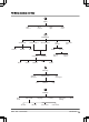

Table Of Contents
- Contents
- Introduction
- Safety
- Installation
- Introduction - Installation
- Main components for installation
- General preparations
- Before the installation of the wires
- Installation of the product
- To put the wire into position with stakes
- To bury the boundary wire or the guide wire
- To extend the boundary wire or the guide wire
- After the installation of the product
- To do the product settings
- Operation
- Maintenance
- Troubleshooting
- Transportation, storage and disposal
- Technical data
- Warranty
- EC Declaration of Conformity

1.3 Product overview
1
3
2
17
26
6
5
4
13
14
12
21
25
19
24
20
23
18
8
10
11
7
22
28
15
29
16
9
27
1. Body
2. Hatch to display, keypad and cutting height
adjustment
3. Stop button
4. Contact strips
5. LED for operation check of the charging
station, boundary wire and guide wire
6. Charging station
7. Carry handle
8. Battery cover
9. Blade disc
10. Skid plate
11. Chassis box with electronics, battery and
motors
12. Main switch
13. Rear wheel
14. Charging strip
15. Keypad
16. Display
17. Loop wire for boundary loop and guide wire
18. Connector for connecting the loop wire to
the charging station
19. Stakes
20. Coupler for the loop wire
21. Screws for securing the charging station
4 - Introduction 1285 - 004 - 16.04.2020