0527SB-LS Owner's Manual / 96193003700
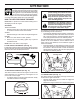
IMPORTANT Safe Operation Practices for Walk-Behind Snow Throwers This snow thrower is capable of amputating hands and feet and throwing objects. Failure to observe the following safety instructions could result in serious injury. WARNING: Snow throwers have exposed rotating parts, which can cause severe injury from contact, or from material thrown from the discharge chute. Keep the area of operation clear of all persons, small children and pets at all times including startup.
6. When cleaning, repairing or inspecting the snow thrower, stop the engine and make certain the collector/impeller and all moving parts have stopped. Disconnect the spark plug wire and keep the wire away from the plug to prevent someone from accidentally starting the engine. 7. Do not run the engine indoors, except when starting the engine and for transporting the snow thrower in or out of the building. Open the outside doors; exhaust fumes are dangerous. 8.
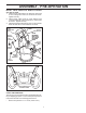
PARTS PACKED SEPARATELY IN CARTON ASSEMBLY / PRE-OPERATION 2. Cut down all four corners of carton and lay panels flat. 3. Remove the two (2) screws securing the auger housing to the pallet. 4. Remove all packing materials except plastic tie holding speed control rod to lower handle. 5. Remove the two (2) plastic ties securing the upper handle to the pallet. 6. Remove snow thrower from carton and check carton thoroughly for additional loose parts.
ASSEMBLY / PRE-OPERATION NOTE: The multi-wrench may be used for assembly of the chute rotator head to snow thrower and making adjustments to the skid plates. INSTALL TRACTION DRIVE CONTROL ROD (See Figs. 3 and 4) The traction drive control rod has the long loop on the end of the spring as shown. 1. Slide rubber sleeve up rod and hook end of spring into pivot bracket with loop opening down as shown. 2.
ASSEMBLY / PRE-OPERATION INSTALL AUGER CONTROL ROD (See Figs. 5 and 6) The auger control rod has the short loop on the end of the spring as shown. 1. Slide rubber sleeve up rod and hook end of spring into control arm with loop opening up as shown. 2. With top end of rod positioned under right side of control panel, push down on rod and insert end of rod into hole in auger control bracket. Secure with retainer spring. INSTALL DISCHARGE CHUTE / CHUTE ROTATER HEAD (See Fig.
ASSEMBLY / PRE-OPERATION INSTALL CHUTE DEFLECTOR REMOTE CONTROL (See Figs. 8 and 9) 1. Install remote cable bracket to discharge chute with 5/16-18 carriage bolt and 5/16-18 locknut as shown. Tighten securely. 2. Install remote cable eyelet to chute deflector with 1/4-20 shoulder bolt, nylon washer and 1/4-20 locknut as shown. Tighten securely. 3. Install spring hooks between hex nuts on chute rotater head and into hole in chute deflector as shown.
OPERATION KNOW YOUR SNOW THROWER READ THIS OWNER'S MANUAL AND ALL SAFETY RULES BEFORE OPERATING YOUR SNOW THROWER. Compare the illustrations with your snow thrower to familiarize yourself with the location of various controls and adjustments. Save this manual for future reference. These symbols may appear on your snow thrower or in literature supplied with the product. Learn and understand their meaning.
OPERATION GASOLINE FILLER CAP AUGER DISCHARGE CHUTE CONTROL LEVER CONTROL DEFLECTOR LEVER TRACTION REMOTE DRIVE SPEED RECOIL DRIVE CONTROL CONTROL LEVER (AUXILIARY) CONTROL LEVER STARTER LEVER HANDLE ELECTRIC START BUTTON MUFFLER CHUTE DEFLECTOR CHOKE CONTROL PRIMER SAFETY IGNITION KEY LH TURN TRIGGER ON / OFF SWITCH DISCHARGE CHUTE LIGHT OIL DRAIN PLUG HANDLE KNOB CLEAN-OUT TOOL NOTE: ITEMS ABOVE ARE SHOWN IN THEIR TYPICAL LOCATION ON THE ENGINE.
OPERATION The operation of any snow thrower can result in foreign objects thrown into the eyes, which can result in severe eye damage. Always wear safety glasses or eye shields while operating your snow thrower or performing any adjustments or repairs. We recommend standard safety glasses or a wide vision safety mask worn over spectacles. TO CONTROL SNOW DISCHARGE (See Fig.
OPERATION • Slower speeds are for heavier snow and faster speeds are for light snow and transporting the snow thrower. It is recommended that you use a slower speed until you are familiar with the operation of the snow thrower. NOTE: When both traction drive and auger control levers are engaged, the traction drive control lever will lock the auger control lever in the engaged position.
OPERATION NOTE: It is not recommended to operate the snow thrower over gravel or rocky surfaces. Objects such as gravel, rocks or other debris, can easily be picked up and thrown by the impeller, which can cause serious personal injury, property damage or damage to the snow thrower. • If snow thrower must be operated over gravel surface, use extra caution and be sure skid plates are adjusted to lowest (highest scraper clearance) position. 1. Shut off engine and wait for all moving parts to stop. 2.
OPERATION TO START ENGINE Your snow thrower engine is equipped with both a 120 Volt A.C. electric starter and a recoil starter. The electric starter is equipped with a three-wire power cord and plug and is designed to operate on 120 Volt A.C. household current. • Be sure your house is a 120 Volt A.C. three-wire grounded system. If you are uncertain, consult a licensed electrician. 6. When the engine starts, release the recoil starter handle and slowly move the choke control to the “OFF” position.
MAINTENANCE GENERAL RECOMMENDATIONS LUBRICATION CHART The warranty on this snow thrower does not cover items that have been subjected to operator abuse or negligence. To receive full value from the warranty, operator must maintain snow thrower as instructed in this manual. Some adjustments will need to be made periodically to properly maintain your snow thrower. At least once a season, check to see if you should make any of the adjustments described in the Service and Adjustments section of this manual.
MAINTENANCE V-BELTS Check V-belts for deterioration and wear after every 50 hours of operation and replace if necessary. The belts are not adjustable. Replace belts if they begin to slip from wear. (See “TO REMOVE BELT COVER” in the Service and Adjustments section of this manual). The V-belts on your snow thrower are of special construction and should be replaced by original equipment manufacturer (OEM) belts available from your nearest dealer.
SERVICE AND ADJUSTMENTS WARNING: To avoid serious injury, before performing any service or adjustments: 1. Be sure the on/off switch is in the OFF position. 2. Remove safety ignition key. 3. Make sure the augers and all moving parts have completely stopped. 4. Disconnect spark plug wire from spark plug and place wire where it cannot come in contact with plug. SNOW THROWER TO ADJUST SNOW THROWER HEIGHT See “TO ADJUST SKID PLATES” and “SCRAPER BAR” in the Operation section of this manual.
SERVICE AND ADJUSTMENTS TO REPLACE BELTS (See Fig. 23) The auger and traction drive belts are not adjustable. If the belts are damaged or begin to slip from wear, they should be replaced. It is recommended that the belt(s) be replaced by a qualified service centre/department. NOTE: It is recommended that both the auger and traction drive belt be replaced at the same time.
TO REMOVE WHEELS (See Fig. 24) • Remove the klik pin and remove wheel from axle. IMPORTANT: When installing wheel, be sure to use the axle hole closest to the end of the shaft – do not use the hole in the wheel hub (if equipped). Inner hole in axle and hole in wheel hub are not used for your model snow thrower. KLIK PIN (INSTALL IN OUTER HOLE OF AXLE ONLY) OUTER HOLE AXLE WHEEL WHEEL HUB FIG.
TROUBLESHOOTING See appropriate section in manual unless directed to a qualified service centre. PROBLEM Does not start CAUSE 1. Fuel shut-off valve (if so equipped) in OFF position. 2. Safety ignition key is not inserted. 3. Out of fuel. 4. Throttle in STOP position. 5. Choke in OFF position. 6. Primer not depressed. 7. Engine is flooded. 8. Spark plug wire is disconnected. 9. Bad spark plug. 10. Stale fuel. 11. Water in fuel. CORRECTION 1. Turn fuel shut-off valve to OPEN position. 2.
REPAIR PARTS AUGER HOUSING / IMPELLER ASSEMBLY SNOW THROWER - MODEL NO. 10527SB-LSb (96193003700), PRODUCT NO. 961 93 00-37 5 11 11 6 7 15 14 16 12 13 8 11 4 12 3 17 10 11 1 9 2 33 32 34 30 31 31 26 36 29 28 27 23 22 21 20 25 35 24 23 22 2 (EXPLODED) 21 18 19 01.07.004-B NOTE: All component dimensions given in U.S. inches. 1 inch = 25.4 mm IMPORTANT: Use only Original Equipment Manufacturer (O.E.M.) replacement parts.
REPAIR PARTS AUGER HOUSING / IMPELLER ASSEMBLY SNOW THROWER - MODEL NO. 10527SB-LSb (96193003700), PRODUCT NO. 961 93 00-37 KEY NO. PART NO.
REPAIR PARTS AUGER HOUSING / IMPELLER ASSEMBLY SNOW THROWER - MODEL NO. 10527SB-LSb (96193003700), PRODUCT NO. 961 93 00-37 1 3 (5x) 4 (5x) KEY NO. PART NO. DESCRIPTION 1 2 3 4 532 42 21-40 532 40 77-27 872 27 05-05 532 15 53-77 AUGER HOUSING SCRAPPER BAR CARRIAGE BOLT 5/16−18 X .625 NUT 5/16−18 2 01.07.022-B 2 3 1 1 2 KEY NO. PART NO. DESCRIPTION 1 2 3 532 18 81-70 532 41 18-33 532 17 95-82 PLASTIC RETAINER AUGER BALL BEARING SCREW 5/16−18 X 1.00 3 01.07.
REPAIR PARTS AUGER HOUSING / IMPELLER ASSEMBLY SNOW THROWER - MODEL NO. 10527SB-LSb (96193003700), PRODUCT NO. 961 93 00-37 2 1 KEY NO. PART NO. DESCRIPTION 1 2 532 42 21-42 532 42 21-43 AUGER ASSEMBLY 27 LH AUGER ASSEMBLY 27 RH 01.07.015-A 2 3 1 3 2 KEY NO. 1 2 3 01.11.002-A PART NO. 532 40 78-34 872 27 05-06 532 75 11-53 DESCRIPTION SKID PLATE CARRIAGE BOLT 5/16−18 X .750 NUT 5/16−18 1 NOTE: All component dimensions given in U.S. inches. 1 inch = 25.
REPAIR PARTS AUGER HOUSING / IMPELLER ASSEMBLY SNOW THROWER - MODEL NO. 10527SB-LSb (96193003700), PRODUCT NO. 961 93 00-37 1 4 5 1 2 3 4 2 3 4 3 KEY NO. PART NO. DESCRIPTION 1 2 3 4 5 532 18 47-47 872 27 05-06 532 17 92-46 810 04 05-00 532 12 86-38 DRIFT CUTTER BAR CARRIAGE BOLT 5/16−18 X .750 PLASTIC WASHER LOCKWASHER 5/16 NUT 5/16−18 5 3 4 01.16.001-A NOTE: All component dimensions given in U.S. inches. 1 inch = 25.4 mm IMPORTANT: Use only Original Equipment Manufacturer (O.E.M.
REPAIR PARTS CONTROL PANEL / DISCHARGE CHUTE SNOW THROWER - MODEL NO. 10527SB-LSb (96193003700), PRODUCT NO. 961 93 00-37 5 7 16 3 18 17 19 6 19 6 *15 *12 *11 2 KEY NO. PART NO.
REPAIR PARTS CONTROL PANEL / DISCHARGE CHUTE SNOW THROWER - MODEL NO. 10527SB-LSb (96193003700), PRODUCT NO. 961 93 00-37 2 2 1 *3 *6 *6 KEY NO. PART NO. DESCRIPTION 1 2 *3 *4 *5 *6 532 42 11-60 817 50 10-10 532 42 06-78 532 42 11-61 532 42 06-75 532 42 11-62 LEVER/CABLE ROTATOR ASSEMBLY GRAY SCREW 10−24 X .625 ROTATOR HEAD ROTATOR PIVOT BRACKET PULLEY PIVOT CABLE ASSEMBLY GRAY *4 01.09.008-B *5 NOTES: 1. ITEMS INDICATED WITH AN * ARE LISTED AS REFERENCE FOR SERVICE PARTS ONLY. 2 1 KEY NO.
REPAIR PARTS HANDLES SNOW THROWER - MODEL NO. 10527SB-LSb (96193003700), PRODUCT NO. 961 93 00-37 10 1 5 6 10 8 7 2 5 3 8 6 9 7 8 4 9 KEY NO. PART NO. DESCRIPTION 1 2 3 4 5 6 7 8 9 10 532 42 17-08 532 42 17-09 532 19 69-44 532 19 69-43 532 41 45-15 874 78 05-12 874 78 05-24 532 75 11-53 532 15 54-15 532 17 87-75 PLOW HANDLE LH PLOW HANDLE RH PANEL BRACKET LH PANEL BRACKET RH HEATED HANDLE GRIP SCREW 5/16−18 X .750 SCREW 5/16−18 X 1.50 NUT 5/16−18 WASHER POP RIVET 1/8 KEY NO. PART NO.
REPAIR PARTS HANDLES SNOW THROWER - MODEL NO. 10527SB-LSb (96193003700), PRODUCT NO. 961 93 00-37 10 2 11 8 4 7 9 9 5 7 6 1 3 13 8 12 13 14 14 12 KEY NO. 1 2 3 4 5 6 7 8 9 10 11 12 13 14 PART NO. 532 41 55-39 532 42 17-06 532 42 17-07 532 41 55-46 532 42 14-92 532 41 26-77 532 42 16-13 532 16 96-75 817 06 04-08 532 41 42-80 532 41 42-81 532 17 88-99 819 13 13-16 872 12 06-18 01.08.
REPAIR PARTS HANDLES SNOW THROWER - MODEL NO. 10527SB-LSb (96193003700), PRODUCT NO. 961 93 00-37 2 1 3 9 8 5 4 7 18 5 18 18 17 19 KEY NO. PART NO.
REPAIR PARTS HANDLES SNOW THROWER - MODEL NO. 10527SB-LSb (96193003700), PRODUCT NO. 961 93 00-37 4 3 2 5 1 6 KEY NO. PART NO. DESCRIPTION 1 2 3 4 5 6 532 41 62-88 532 41 45-72 532 17 88-31 532 16 96-75 817 06 04-10 532 42 18-14 INTERLOCK SPRING INTERLOCK CAM TORSION SPRING RETAINER SCREW 1/4−20 X .625 INTERLOCK STOP KEY NO. PART NO.
REPAIR PARTS DRIVE SNOW THROWER - MODEL NO. 10527SB-LSb (96193003700), PRODUCT NO. 961 93 00-37 24 23 27 3 21 25 1 28 28 27 14 26 28 28 1 16 2 2 17 3 1 15 2 20 3 2 11 8 2 14 12 8 14 13 1 1 2 22 2 2 1 18 19 10 9 8 1 4 7 4 5 6 2 1 3 4 5 01.02.001-F_Sheet_1 KEY NO. PART NO. DESCRIPTION KEY NO. PART NO.
REPAIR PARTS DRIVE SNOW THROWER - MODEL NO. 10527SB-LSb (96193003700), PRODUCT NO. 961 93 00-37 2 2 1 42 20 43 41 40 32 32 20 41 38 3 37 39 7 4 36 5 6 12 7 35 34 29 15 31 8 9 14 15 7 28 32 10 11 13 15 14 33 30 17 15 16 26 8 23 17 18 19 27 20 21 44 22 25 01.02.001-F_Sheet_2 15 24 13 NOTE: All component dimensions given in U.S. inches. 1 inch = 25.4 mm IMPORTANT: Use only Original Equipment Manufacturer (O.E.M.) replacement parts.
REPAIR PARTS DRIVE SNOW THROWER - MODEL NO. 10527SB-LSb (96193003700), PRODUCT NO. 961 93 00-37 KEY NO. PART NO.
REPAIR PARTS DRIVE SNOW THROWER - MODEL NO. 10527SB-LSb (96193003700), PRODUCT NO. 961 93 00-37 6 7 1b 4 8 3 1b 7 1a 2 3 5 4 6 01.03.001-A KEY NO. PART NO. DESCRIPTION 1 1a 1b 2 3 4 5 6 7 8 532 40 49-23 532 40 43-07 532 18 42-06 532 18 00-81 532 17 46-97 532 17 98-30 532 14 63-15 817 49 05-08 532 15 54-43 532 18 92-82 (assy of 1a,1b) AXLE ASSEMBLY AXLE SHAFT ROLL PIN 3/16 GEAR THRUST WASHER AXLE BEARING SCREW 5/16−18 X .625 BOLT 5/16−18 X .
REPAIR PARTS CHASSIS / ENGINE / PULLEYS SNOW THROWER - MODEL NO. 10527SB-LSb (96193003700), PRODUCT NO. 961 93 00-37 5 3 4 5 4 1 6 6 01.00.016-A 2 KEY NO. PART NO. - --- -- ---- 1 2 3 4 5 6 532 41 53-40 532 41 08-77 532 41 70-71 532 15 04-06 532 15 00-78 532 18 44-71 ENGINE, B & S MODEL 20M314-1237-E1 FRAME BOTTOM PAN ENGINE MOUNT PLATE BOLT 3/8−16 SCREW 5/16−18 X .750 SCREW 10−24 X .625 KEY NO. PART NO.
REPAIR PARTS WHEELS SNOW THROWER - MODEL NO. 10527SB-LSb (96193003700), PRODUCT NO. 961 93 00-37 2 17 20 16 18 15 18 24 17 16 20 19 2 3 2 1 4 5 6 23 22 19 7 8 9 7 22 11 21 21 11 10 4 23 14 12 13 13 14 10 9 6 3 2 1 5 8 12 01.15.001-A KEY NO. PART NO.
REPAIR PARTS WHEELS SNOW THROWER - MODEL NO. 10527SB-LSb (96193003700), PRODUCT NO. 961 93 00-37 1 KEY NO. PART NO. DESCRIPTION 1 2 532 41 52-63 532 18 78-59 STEER CABLE BRACKET LH STEER CABLE BRACKET RH KEY NO. PART NO. DESCRIPTION 1 2 532 19 94-99 532 19 95-00 WHEEL 16 X 4.80 X LH WHEEL 16 X 4.80 X RH 2 01.15.002-A 1 2 01.06.005-A NOTE: All component dimensions given in U.S. inches. 1 inch = 25.4 mm IMPORTANT: Use only Original Equipment Manufacturer (O.E.M.) replacement parts.
REPAIR PARTS BAG OF PARTS SNOW THROWER - MODEL NO. 10527SB-LSb (96193003700), PRODUCT NO. 961 93 00-37 4 14 13 12 6 5 9 8 3 10 2 11 7 KEY NO. PART NO.
REPAIR PARTS DECALS SNOW THROWER - MODEL NO. 10527SB-LSb (96193003700), PRODUCT NO. 961 93 00-37 1 2 4 7 9 12 6 1 3 5 10 KEY NO. PART NO. DESCRIPTION 1 2 3 4 5 6 7 9 10 11 12 --- 532 18 10-37 532 42 37-10 532 18 10-35 532 18 10-42 532 42 37-09 532 18 10-33 532 41 54-55 532 41 54-75 532 18 37-30 532 41 53-99 532 41 53-98 532 42 35-13 532 42 35-14 DECAL, DANGER DECAL, AUGER, 10527SB-LSb HUSQ. USA DECAL, DANGER, DEFLECTOR DECAL, DANGER DECAL, CONSOLE, 10527SB-LSb HUSQ.
532 42 35-13 09.23.08 SBW Printed in the U.S.A.