0530SBEB Owner's Manual
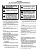
IMPORTANT Safe Operation Practices for Walk-Behind Snow Throwers This snow thrower is capable of amputating hands and feet and throwing objects. Failure to observe the following safety instructions could result in serious injury. WARNING: Snow throwers have exposed rotating parts, which can cause severe injury from contact, or from material thrown from the discharge chute. Keep the area of operation clear of all persons, small children and pets at all times including startup.
6. When cleaning, repairing or inspecting the snow thrower, stop the engine and make certain the collector/impeller and all moving parts have stopped. Disconnect the spark plug wire and keep the wire away from the plug to prevent someone from accidentally starting the engine. 7. Do not run the engine indoors, except when starting the engine and for transporting the snow thrower in or out of the building. Open the outside doors; exhaust fumes are dangerous. 8.
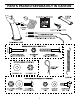
PARTS PACKED SEPARATELY IN CARTON 4
ASSEMBLY / PRE-OPERATION Read these instructions and this manual in its entirety before you attempt to assemble or operate your new snow thrower. Reading the entire manual will familiarize you with the unit, which will assist you in assembly, operation and maintenance of the product. Your new snow thrower has been assembled at the factory with the exception of those parts left unassembled for shipping purposes. All parts such as nuts, washers, bolts, etc.
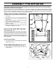
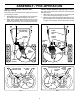
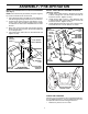
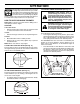
ASSEMBLY / PRE-OPERATION INSTALL TRACTION DRIVE CONTROL ROD (See Figs. 3 and 4) The traction drive control rod has the long loop on the end of the spring as shown. 1. Slide rubber sleeve up rod and hook end of spring into pivot bracket with loop opening down as shown. 2. With top end of rod positioned under left side of control panel, push rod down and insert top end of rod into hole in drive control bracket. Secure with retainer spring. INSTALL AUGER CONTROL ROD (See Figs.
ASSEMBLY / PRE-OPERATION INSTALL DISCHARGE CHUTE / CHUTE ROTATER HEAD (See Fig. 7) NOTE: The multi-wrench provided in your parts bag may be used to install the chute rotater head. 1. Place discharge chute assembly on top of chute base with discharge opening toward front of snow thrower. 2. Position chute rotater head over chute bracket. If necessary, rotate chute assembly to align square and pin on underside of chute rotater head with holes in chute bracket. 3.
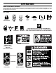
OPERATION KNOW YOUR SNOW THROWER READ THIS OWNER'S MANUAL AND ALL SAFETY RULES BEFORE OPERATING YOUR SNOW THROWER. Compare the illustrations with your snow thrower to familiarize yourself with the location of various controls and adjustments. Save this manual for future reference. These symbols may appear on your snow thrower or in literature supplied with the product. Learn and understand their meaning.
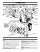
OPERATION GASOLINE FILLER CAP ELECTRIC START BUTTON AUGER DISCHARGE CHUTE CONTROL LEVER CONTROL DEFLECTOR REMOTE LEVER DRIVE SPEED RECOIL CONTROL LEVER CONTROL LEVER (AUXILIARY) STARTER HANDLE TRACTION CHUTE DRIVE DEFLECTOR CONTROL LEVER MUFFLER CHOKE CONTROL PRIMER LH TURN TRIGGER SAFETY IGNITION KEY FUEL SHUT-OFF VALVE LIGHT DISCHARGE CHUTE ON / OFF SWITCH HANDLE KNOB CLEAN-OUT TOOL MUFFLER NOTE: ITEMS ABOVE ARE SHOWN IN THEIR TYPICAL LOCATION ON THE ENGINE.
OPERATION The operation of any snow thrower can result in foreign objects thrown into the eyes, which can result in severe eye damage. Always wear safety glasses or eye shields while operating your snow thrower or performing any adjustments or repairs. We recommend standard safety glasses or a wide vision safety mask worn over spectacles. TO CONTROL SNOW DISCHARGE (See Fig.
OPERATION TO MOVE FORWARD AND BACKWARD (See Fig. 16) SELF-PROPELLING, forward and reverse movement of the snow thrower, is controlled by the traction drive control lever located on the left side handle. • Squeeze traction drive control lever to handle to engage the drive system. • Release traction drive control lever to stop the forward or reverse movement of the snow thrower. SPEED and DIRECTION are controlled by the drive speed control lever.
OPERATION TO ADJUST SKID PLATES (See Fig. 18) NOTE: The wrench provided in your parts bag may be used to adjust the skid plates. Skid plates are located on each side of the auger housing and adjust the clearance between the scraper bar and the ground surface. Adjust skid plates evenly to proper height for current surface conditions.
OPERATION COLD START - ELECTRIC STARTER 1. Insert safety ignition key (packed separately in parts bag) into ignition slot until it clicks. DO NOT turn the key. Keep the extra safety ignition key in a safe place. 2. Place ON / OFF switch in “ON” position. 3. Rotate choke control to “FULL” position. 4. Connect the power cord to the engine. 5. Plug the other end of the power cord into a three-hole grounded 120 Volt A.C. receptacle. NOTE: Do not use primer when starting engine with the electric starter. 6.
MAINTENANCE GENERAL RECOMMENDATIONS LUBRICATION CHART The warranty on this snow thrower does not cover items that have been subjected to operator abuse or negligence. To receive full value from the warranty, operator must maintain snow thrower as instructed in this manual. Some adjustments will need to be made periodically to properly maintain your snow thrower. At least once a season, check to see if you should make any of the adjustments described in the Service and Adjustments section of this manual.
MAINTENANCE V-BELTS Check V-belts for deterioration and wear after every 50 hours of operation and replace if necessary. The belts are not adjustable. Replace belts if they begin to slip from wear. (See “TO REMOVE BELT COVER” in the Service and Adjustments section of this manual). The V-belts on your snow thrower are of special construction and should be replaced by original equipment manufacturer (OEM) belts available from your nearest dealer.
SERVICE AND ADJUSTMENTS 1. Disengage all controls and move throttle control to STOP position. Wait for all moving parts to stop. 2. Disconnect spark plug wire from spark plug and place wire where it cannot come in contact with plug. 3. Align holes in impeller hub with holes in impeller shaft and install two (2) new 1/4-20 x 1-5/8" capscrew/shear bolts. Install 1/4-20 locknuts and tighten securely. WARNING: To avoid serious injury, before performing any service or adjustments: 1.
SERVICE AND ADJUSTMENTS TO REPLACE BELTS (See Fig. 22) The auger and traction drive belts are not adjustable. If the belts are damaged or begin to slip from wear, they should be replaced. It is recommended that the belt(s) be replaced by a qualified service center. NOTE: It is recommended that both the auger and traction drive belt be replaced at the same time.
TO REMOVE WHEELS (See Fig. 23) • Remove the klik pin and remove wheel from axle. IMPORTANT: When installing wheel, be sure to use the axle hole closest to the end of the shaft – do not use the hole in the wheel hub (if equipped). Inner hole in axle and hole in wheel hub are not used for your model snow thrower. KLIK PIN (INSTALL IN OUTER HOLE OF AXLE ONLY) OUTER HOLE AXLE WHEEL HUB WHEEL FIG.
TROUBLESHOOTING See appropriate section in manual unless directed to an authorized service centre/department. PROBLEM Does not start Loss of power CAUSE 1. Fuel shut-off valve (if so equipped) in OFF position. 2. Safety ignition key is not inserted. 3. Out of fuel. 4. Throttle in STOP position (or ON/OFF switch is OFF). 5. Choke in OFF position. 6. Primer not depressed. 7. Engine is flooded. 8. Spark plug wire is disconnected. 9. Bad spark plug. 10. Stale fuel. 11. Water in fuel. CORRECTION 1.
REPAIR PARTS AUGER HOUSING / IMPELLER ASSEMBLY SNOW THROWER - MODEL NO. 10530SBEB (96193001300), PRODUCT NO.
REPAIR PARTS AUGER HOUSING / IMPELLER ASSEMBLY SNOW THROWER - MODEL NO. 10530SBEB (96193001300), PRODUCT NO. 961 93 00-13 KEY NO. 4 5 6 7 8 9 10 11 12 13 14 15 16 18 19 20 21 22 23 24 25 26 27 28 29 30 31 32 33 34 35 36 37 38 39 40 41 42 43 44 45 46 47 48 49 50 51 53 54 55 56 57 PART NO.
REPAIR PARTS CONTROL PANEL / DISCHARGE CHUTE SNOW THROWER - MODEL NO. 10530SBEB (96193001300), PRODUCT NO.
REPAIR PARTS CONTROL PANEL / DISCHARGE CHUTE SNOW THROWER - MODEL NO. 10530SBEB (96193001300), PRODUCT NO. 961 93 00-13 KEY PART NO. NO.
REPAIR PARTS HANDLES SNOW THROWER - MODEL NO. 10530SBEB (96193001300), PRODUCT NO.
REPAIR PARTS HANDLES SNOW THROWER - MODEL NO. 10530SBEB (96193001300), PRODUCT NO. 961 93 00-13 KEY PART NO. NO.
REPAIR PARTS DRIVE SNOW THROWER - MODEL NO. 10530SBEB (96193001300), PRODUCT NO.
REPAIR PARTS DRIVE SNOW THROWER - MODEL NO. 10530SBEB (96193001300), PRODUCT NO. 961 93 00-13 KEY PART NO. NO.
REPAIR PARTS CHASSIS / ENGINE / PULLEYS SNOW THROWER - MODEL NO. 10530SBEB (96193001300), PRODUCT NO.
REPAIR PARTS CHASSIS / ENGINE / PULLEYS SNOW THROWER - MODEL NO. 10530SBEB (96193001300), PRODUCT NO. 961 93 00-13 KEY PART NO. NO.
REPAIR PARTS WHEELS / DECALS SNOW THROWER - MODEL NO. 10530SBEB (96193001300), PRODUCT NO.
REPAIR PARTS WHEELS / DECALS SNOW THROWER - MODEL NO. 10530SBEB (96193001300), PRODUCT NO. 961 93 00-13 KEY PART NO. NO.
532 40 37-62 Rev. 3 06.06.06 BY Printed in U.S.A. The product must exhibit reasonable care, maintenance, operation, storage and general upkeep as written in the maintenance section of the Owner’s/Operator’s manual. Should an operational problem or failure occur, the product should not be used, but delivered as is to an authorized Husqvarna dealer for evaluation. Proof of purchase, as explained in section 6, rests solely with the customer.