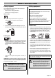
Operator’s manual (EPA) 123C 123L 123LD Please read the operator’s manual carefully and make sure you understand the instructions before using the machine.
KEY TO SYMBOLS Symbols Only intended for trimmer heads. WARNING! Clearing saws, brushcutters and trimmers can be dangerous! Careless or incorrect use can result in serious or fatal injury to the operator or others. Please read the operator’s manual carefully and make sure you understand the instructions before using the machine. Other symbols/decals on the machine refer to special certification requirements for certain markets.
CONTENTS Contents KEY TO SYMBOLS Symbols ........................................................................ CONTENTS Contents ....................................................................... Note the following before starting: ................................. SAFETY INSTRUCTIONS Personal protective equipment ...................................... Machine′s safety equipment ......................................... Checking, maintaining and servicing the machine′s safety equipment .............
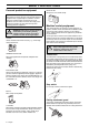
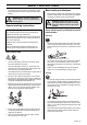
SAFETY INSTRUCTIONS Personal protective equipment FIRST AID KIT Always have a first aid kit nearby. IMPORTANT! Whenever you use a clearing saw, brushcutter or trimmer you must wear personal protective equipment that is approved by the authorities. Personal protective equipment does not eliminate the risk of accidents, but it can reduce the effects of an injury in the event of an accident. Ask your dealer for help when choosing protective equipment.
SAFETY INSTRUCTIONS ! WARNING! Never use a cutting attachment without an approved guard. See the chapter on Technical data. If an incorrect or faulty guard is fitted this can cause serious personal injury. Vibration damping system For mufflers it is very important that you follow the instructions on checking, maintaining and servicing your machine. See instructions under the heading Checking, maintaining and servicing the machine’s safety equipment.
SAFETY INSTRUCTIONS Checking, maintaining and servicing the machine′s safety equipment IMPORTANT! All servicing and repair work on the machine requires special training. This is especially true of the machine′s safety equipment. If your machine fails any of the checks described below you must contact your service agent. When you buy any of our products we guarantee the availability of professional repairs and service.
SAFETY INSTRUCTIONS Cutting equipment Cutting equipment This section describes how to choose and maintain your cutting equipment in order to: • Obtain maximum cutting performance. • Extend the life of cutting equipment. IMPORTANT! This section describes how to choose and maintain your cutting equipment in order to: Reduce the risk of kickback. General rules Obtain maximum cutting performance. Extend the life of cutting equipment.
SAFETY INSTRUCTIONS General safety precautions (CAUTION! Not with your foot). Then grip the starter handle with your right hand and pull the starter cord. Never wrap the starter cord around your hand IMPORTANT! The machine is only designed for trimming grass. The only accessories you can operate with this engine unit are the cutting attachments we recommend in the chapter on Technical data.
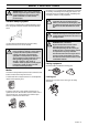
SAFETY INSTRUCTIONS • The transport guard must always be fitted to the cutting attachment when the machine is being transported or in storage. ! Basic working techniques • WARNING! Take care when handling fuel. Bear in mind the risk of fire, explosion and inhaling fumes. ! General working instructions IMPORTANT! This section describes the basic safety precautions for working with clearing saws and trimmers. If you encounter a situation where you are uncertain how to proceed you should ask an expert.
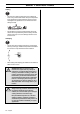
SAFETY INSTRUCTIONS Cutting • The trimmer is ideal for cutting grass that is difficult to reach using a normal lawn mower. Keep the cord parallel to the ground when cutting. Avoid pressing the trimmer head against the ground as this can ruin the lawn and damage the tool. • Do not allow the trimmer head to constantly come into contact with the ground during normal cutting. Constant contact of this type can cause damage and wear to the trimmer head.
WHAT IS WHAT? LD C What is what? 1 Trimmer head 12 Fuel tank 2 Grease filler cap 13 Choke control 3 Bevel gear 14 Air purge 4 Cutting attachment guard 15 Air filter cover 5 Shaft 16 Handle adjustment 6 Loop handle 17 Drive disc 7 Throttle control 18 Socket spanner 8 Stop switch 19 Operator’s manual (EPA) 9 Throttle lock 20 Allen key 10 Cylinder cover 21 Locking pin 11 Starter handle 22 Shaft coupling English – 11
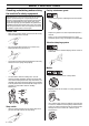
ASSEMBLY Fitting the loop handle • • Hold both parts of the shaft and pull the lower part of the shaft out of the coupling. Position the handle on the shaft. Note that the handle must be mounted below the arrow on the shaft. ! • Fit the screw, securing plate and wing nut as shown in the diagram. • Tighten the wing nut. Assembling and dismantling the two-piece shaft WARNING! Never use a cutting attachment without an approved guard. See the chapter on Technical data.
ASSEMBLY Fitting the trimmer guard and trimmer head (123C) Guard • Fit the guard as shown in the diagram. Tighten securely. Trimmer head • Fit the dust cup on the shaft. The nut must be completely covered by the dust cup. • Hold the dust cup with a spanner to prevent the shaft from rotating. • Screw the trimmer head onto the shaft.
FUEL HANDLING Fuel Two-stroke oil CAUTION! The machine is equipped with a two-stroke engine and must always been run using a mixture of gasoline and two-stroke engine oil. It is important to accurately measure the amount of oil to be mixed to ensure that the correct mixture is obtained. When mixing small amounts of fuel, even small inaccuracies can drastically affect the ratio of the mixture.
FUEL HANDLING Fuelling ! WARNING! Taking the following precautions, will lessen the risk of fire: Do not smoke or place hot objects near fuel. Always shut off the engine before refuelling. Always stop the engine and let it cool for a few minutes before refuelling. When refuelling, open the fuel cap slowly so that any excess pressure is released gently. Tighten the fuel cap carefully after refuelling. Always move the machine away from the refuelling area before starting.
STARTING AND STOPPING Check before starting • • Check that the support flange is not cracked due to fatigue or due to being tightened too much. Discard the support flange if it is cracked. Starting and stopping ! WARNING! The complete clutch cover and shaft must be fitted before the machine is started, otherwise the clutch can come loose and cause personal injury. Always move the machine away from the refuelling area before starting. Place the machine on a flat surface.
STARTING AND STOPPING Warm engine Starting Ignition: Hold the body of the machine on the ground using your left hand (CAUTION! Not with your foot!). Grip the starter handle, slowly pull out the cord with your right hand until you feel some resistance (the starter pawls grip), now quickly and powerfully pull the cord. Never wrap the starter cord around your hand Set the stop switch to the start position. Repeat pulling the cord until the engine starts. When the engine starts.
MAINTENANCE Carburettor Basic setting Your Husqvarna product has been designed and manufactured to specifications that reduce harmful emissions. After the engine has used 8-10 tanks of fuel the engine will be run-in. To ensure that it continues to run at peak performance and to minimise harmful exhaust emissions after the running-in period, ask your dealer/service workshop (who will have a rev counter at their disposal) to adjust your carburettor.
MAINTENANCE Fine adjustment of the idle speed T Correctly adjusted carburettor Adjust the idle speed using the idle adjustment screw T, if it is necessary to readjust. First turn the idle adjustment screw T clockwise until the cutting attachment starts to rotate. Then turn the screw anticlockwise until the cutting attachment stops. The idle speed is correctly adjusted when the engine will run smoothly in every position.
MAINTENANCE Cooling system Two-piece shaft (123LD) To keep the working temperature as low as possible the machine is equipped with a cooling system. 4 3 The drive shaft end in the lower shaft should be lubricated with grease every 30 hours. There is a risk that the drive shaft ends (splined coupling) on models with two-piece shafts will seize if they are not lubricated regularly. 2 1 Air filter The cooling system consists of: 1 Air intake on the starter. 2 Fins on the flywheel.
MAINTENANCE Put the filter in a plastic bag and pour the filter oil over it. Knead the plastic bag to distribute the oil. Squeeze the excess oil out of the filter inside the plastic bag and pour off the excess before fitting the filter to the machine. Never use common engine oil. This would drain through the filter quite quickly and collect in the bottom. Bevel gear • Check that nuts and screws are tight. • Check that the screws that hold the bevel gear are tight.
TECHNICAL DATA Technical data 123C 123L 123LD 1,50/24,5 1,50/24,5 1,50/24,5 Engine Cylinder volume, cu.in/cm3 Cylinder bore, inch/mm 1,34/34,0 1,34/34,0 1,34/34,0 Stroke, inch/mm 1,06/27 1,06/27 1,06/27 Idle speed, rpm 2700 2700 2700 Recommended max. speed, rpm 11000-11700 11000-11700 11000-11700 Speed of output shaft, rpm 11700 8014 8014 Max. engine output, acc.
TECHNICAL DATA 123C Approved accessories Type Cutting attachment guard, Art. no. Trimmy Hit VII (R) 537 02 61-01 Type Cutting attachment guard, Art. no. Trimmer head T35 503 93 42-02 / 503 97 71-01 Plastic blades Tricut Ø 300 mm 503 93 42-02 Attachments Art No.
FEDERAL EMISSION CONTROL WARRANTY STATEMENT YOUR WARRANTY RIGHTS AND OBLIGATIONS The EPA (The US Environmental Protection Agency), Environment Canada and Husqvarna Forest & Garden are pleased to explain the emissions control system warranty on your 2001 and later small nonroad engine. In U.S. and Canada, new small nonroad engines must be designed, built and equipped to meet the federal stringent anti-smog standards.
T35 2 3 2,4-2,7 mm .095-.
Trimmy VII 2 3 2,0- mm ,080-.
1140223-95 ´®z+H6G¶5I¨ ´®z+H6G¶5I¨ 2003-11-07