Operator’s Manual 12527HV Gasoline containing up to 10% ethanol (E10) is acceptable for use in this machine. The use of any gasoline exceeding 10% ethanol (E10) will void the product warranty. 532 44 34-58 Please read the owner's manual carefully and make sure you understand the instructions before using the machine.
IMPORTANT Safe Operation Practices for Walk-Behind Snow Throwers This snow thrower is capable of amputating hands and feet and throwing objects. Failure to observe the following safety instructions could result in serious injury. WARNING: Snow throwers have exposed rotating parts, which can cause severe injury from contact, or from material thrown from the discharge chute. Keep the area of operation clear of all persons, small children and pets at all times including startup.
6. When cleaning, repairing or inspecting the snow thrower, stop the engine and make certain the collector/impeller and all moving parts have stopped. Disconnect the spark plug wire and keep the wire away from the plug to prevent someone from accidentally starting the engine. 7. Do not run the engine indoors, except when starting the engine and for transporting the snow thrower in or out of the building. Open the outside doors; exhaust fumes are dangerous. 8.
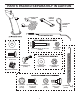
PARTS PACKED SEPARATELY IN CARTON (1) POWER CORD (198563) (1) MULTIWRENCH (180684) (3) RETAINER SPRINGS (169675) (6) SHEAR BOLTS 1/4-20 x 1-3/4 (192090) (2) FLAT WASHERS (6) LOCKNUTS 1/4-20 (73800400) (2) CARRIAGE BOLTS 3/8-16 x 2.
ASSEMBLY / PRE-OPERATION Read these instructions and this manual in its entirety before you attempt to assemble or operate your new snow thrower. Reading the entire manual will familiarize you with the unit, which will assist you in assembly, operation and maintenance of the product. Your new snow thrower has been assembled at the factory with the exception of those parts left unassembled for shipping purposes. All parts such as nuts, washers, bolts, etc.
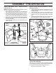
ASSEMBLY / PRE-OPERATION INSTALL AUGER CONTROL ROD (See Figs. 5 and 6) 1. Retrieve vinyl sleeve and spring from bag of parts and retrieve the auger control rod from carton chute tray. Slide straight rod end through the small hole in the vinyl sleeve. Hook spring in hole in rod end. 2. Hook end of spring into control arm with loop opening up as shown. (See Fig. 5) 3. With top end of rod positioned under right side of control panel, push down on rod and insert end of rod into hole in auger control bracket.
ASSEMBLY / PRE-OPERATION INSTALL DISCHARGE CHUTE / CHUTE ROTATOR HEAD (See Fig. 7) NOTE: The multi-wrench provided in your parts bag may be used to install the chute rotator head. 1. Place discharge chute assembly on top of chute base with discharge opening toward front of snow thrower. 2. Position chute rotator head over chute bracket. If necessary, rotate chute assembly to align square and pin on underside of chute rotator head with holes in chute bracket. 3.
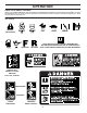
OPERATION KNOW YOUR SNOW THROWER READ THIS OWNER'S MANUAL AND ALL SAFETY RULES BEFORE OPERATING YOUR SNOW THROWER. Compare the illustrations with your snow thrower to familiarize yourself with the location of various controls and adjustments. Save this manual for future reference. These symbols may appear on your snow thrower or in literature supplied with the product. Learn and understand their meaning.
OPERATION ELECTRIC START BUTTON MUFFLER GASOLINE FILLER CAP AUGER CONTROL LEVER POWER CORD PLUG CHOKE CONTROL DISCHARGE CHUTE CONTROL LEVER DRIVE SPEED CONTROL LEVER DEFLECTOR REMOTE CONTROL LEVER TRACTION DRIVE CONTROL LEVER CHUTE DEFLECTOR SAFETY IGNITION KEY LH TURN TRIGGER ON / OFF SWITCH DISCHARGE CHUTE PRIMER FUEL SHUT-OFF VALVE LIGHT RECOIL (AUXILIARY) STARTER HANDLE CLEAN-OUT TOOL HANDLE KNOB NOTE: ITEMS ABOVE ARE SHOWN IN THEIR TYPICAL LOCATION ON THE ENGINE.
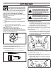
OPERATION The operation of any snow thrower can result in foreign objects thrown into the eyes, which can result in severe eye damage. Always wear safety glasses or eye shields while operating your snow thrower or performing any adjustments or repairs. We recommend standard safety glasses or a wide vision safety mask worn over spectacles. TO CONTROL SNOW DISCHARGE (See Fig.
OPERATION TO MOVE FORWARD AND BACKWARD (See Fig. 16) SELF-PROPELLING, forward and reverse movement of the snow thrower, is controlled by the traction drive control lever located on the left side handle. • Squeeze traction drive control lever to handle to engage the drive system. • Release traction drive control lever to stop the forward or reverse movement of the snow thrower. SPEED and DIRECTION are controlled by the drive speed control lever.
OPERATION BEFORE STARTING THE ENGINE TO ADJUST SKID PLATES (See Fig. 18) NOTE: The wrench provided in your parts bag may be used to adjust the skid plates. Skid plates are located on each side of the auger housing and adjust the clearance between the scraper bar and the ground surface. Adjust skid plates evenly to proper height for current surface conditions.
OPERATION TO START ENGINE • Be sure fuel shut-off valve is in the “OPEN” position. Your snow thrower engine is equipped with both a 120 Volt A.C. electric starter and a recoil starter. The electric starter is equipped with a three-wire power cord and plug and is designed to operate on 120 Volt A.C. household current. • Be sure your house is a 120 Volt A.C. three-wire grounded system. If you are uncertain, consult a licensed electrician. 6.
MAINTENANCE LUBRICATION CHART GENERAL RECOMMENDATIONS The warranty on this snow thrower does not cover items that have been subjected to operator abuse or negligence. To receive full value from the warranty, operator must maintain snow thrower as instructed in this manual. Some adjustments will need to be made periodically to properly maintain your snow thrower. All adjustments in the Service and Adjustments section of this manual should be checked at least once each season.
MAINTENANCE SNOW THROWER Check the crankcase oil level before starting the engine and after each five (5) hours of continuous use. Tighten oil fill cap / dipstick securely each time you check the oil level. TO CHANGE ENGINE OIL Determine temperature range anticipated before next oil change. All oil must meet API service classification SG–SL. • Be sure snow thrower is on level surface. • Oil will drain more freely when warm. • Catch oil in a suitable container.
SERVICE AND ADJUSTMENTS WARNING: To avoid serious injury, before performing any service or adjustments: 1. Be sure the on/off switch is in the OFF position. 2. Remove safety ignition key. 3. Make sure the augers and all moving parts have completely stopped. 4. Disconnect spark plug wire from spark plug and place wire where it cannot come in contact with plug. SNOW THROWER TO ADJUST SNOW THROWER HEIGHT See “TO ADJUST SKID PLATES” and “SCRAPER BAR” in the Operation section of this manual.
SERVICE AND ADJUSTMENTS TO REPLACE BELTS (See Fig. 22) The auger and traction drive belts are not adjustable. If the belts are damaged or begin to slip from wear, they should be replaced. It is recommended that the belt(s) be replaced by a service center/department. NOTE: It is recommended that both the auger and traction drive belt be replaced at the same time.
SERVICE AND ADJUSTMENTS ENGINE SPEED Never tamper with the engine governor, which is factory set for proper engine speed. Overspeeding the engine above the factory high speed setting can be dangerous and will void the warranty. If you think the engine-governed high speed needs adjusting, contact a qualified service center, which has proper equipment and experience to make any necessary adjustments. TO REMOVE WHEELS (See Fig. 23) • Remove the wheel pin and retainer pin and remove wheel from axle.
STORAGE • Empty the fuel tank by starting the engine and letting it run until the fuel lines and carburetor are empty. • Never use engine or carburetor cleaner products in the fuel tank or permanent damage may occur. • Use fresh fuel next season. NOTE: Fuel stabilizer is an acceptable alternative in minimizing the formation of fuel gum deposits during storage. Add stabilizer to gasoline in fuel tank or storage container. Always follow the mix ratio found on stabilizer container.
TROUBLESHOOTING See appropriate section in manual unless directed to a service center/department. PROBLEM CAUSE CORRECTION Does not start 1. Fuel shut-off valve (if so equipped) in OFF position. 1. Turn fuel shut-off valve to OPEN position. 2. Safety ignition key is not inserted. 2. Insert safety ignition key. 3. Out of fuel. 3. Fill fuel tank with fresh, clean gasoline. 4. Throttle in STOP position (or ON/ OFF switch is OFF). 4. Move throttle to FAST position (or ON/OFF switch to ON position).
SERVICE NOTES 21
&RQVXPHU :KHHOHG 3URGXFWV ± /LPLWHG :DUUDQW\ +XVTYDUQD ZDUUDQWV WR WKH RULJLQDO UHWDLO SXUFKDVHU WKDW WKLV +XVTYDUQD SURGXFW LV IUHH IURP GHIHFWV LQ PDWHULDO RU ZRUNPDQVKLS XQGHU QRUPDO XVH DQG PDLQWHQDQFH IURP WKH GDWH RI UHWDLO SXUFKDVH IRU WKH DSSOLFDEOH :DUUDQW\ 3HULRG VKRZQ RQ ([KLELW $ &HUWDLQ FRPSRQHQWV H J HQJLQHV DQG WUDQVPLVVLRQV DUH H[FOXGHG IURP FRYHUDJH DQG RWKHU OLPLWDWLRQV DSSO\ DV GHVFULEHG LQ WKLV GRFXPHQW +XVTYDUQD ZLOO UHSDLU RU UHSODFH DW LWV GLVFUHWLRQ DQ\ GHIHFWLYH SURG
F 3UHYHQWDWLYH PDLQWHQDQFH DV RXWOLQHG LQ WKH RSHUDWRU¶V PDQXDO ,Q DGGLWLRQ \RX PXVW FHDVH XVLQJ WKH SURGXFW LPPHGLDWHO\ XSRQ DQ\ IDLOXUH RU GDPDJH 7KH SURGXFW VKRXOG EH WDNHQ WR DQ DXWKRUL]HG +XVTYDUQD VHUYLFLQJ GHDOHU SULRU WR DQ\ IXUWKHU XVH 'DPDJHV UHVXOWLQJ IURP QRUPDO DJLQJ ZHDU DQG WHDU RU QHJOHFW DUH 127 FRYHUHG 7KH /LPLWHG :DUUDQW\ GRHV QRW FRYHU GDPDJH RWKHU WKDQ WKDW UHVXOWLQJ IURP GHIHFWV LQ PDWHULDO RU ZRUNPDQVKLS 7KH IROORZLQJ DUH 127 FRQVL
&RQVXPHU :KHHOHG :DUUDQW\ &KDUW ([KLELW $ &RQVXPHU SHUVRQDO KRXVHKROG XVH RQO\ 3URGXFW &RPSRQHQW 5LGLQJ /DZQ 7UDFWRUV )UDPH &KDVVLV )URQW $[OH (QJLQH 7UDQVPLVVLRQ LI PDGH E\ +XVTYDUQD 3HHUOHVV 7UDQVPLVVLRQ LI WKLUG SDUW\ %DWWHU\ 2WKHU 1RQ ([SHQGDEOH &RPSRQHQWV 5HVLGHQWLDO =HUR 7XUQ 0RZHUV 5= 2QO\ (QJLQH 7UDQVPLVVLRQ %DWWHU\ 2WKHU 1RQ ([SHQGDEOH &RPSRQHQWV 5HVLGHQWLDO =HUR 7XUQ 0RZHUV 0= (= (QJLQH 7UDQVPLVVLRQ %DWWHU\ 2WKHU 1RQ ([SHQGDEOH &RPSRQHQWV /( (GJHU (QJLQH
&RQVXPHU :KHHOHG :DUUDQW\ &KDUW ([KLELW $ &RQVXPHU SHUVRQDO KRXVHKROG XVH RQO\ &RPPHUFLDO DQ\ FRPPHUFLDO 5HQWDO DQ\ UHQWDO SURIHVVLRQDO LQVWLWXWLRQDO XVDJH DULJFXOXWUDO RU LQFRPH SURGXFLQJ XVH RWKHU WKDQ 5HQWDO 8VH 3URGXFW &RPSRQHQW )URQW 0RXQWHG 'HFN 5LGHUV (QJLQH 7UDQVPLVVLRQ
SERVICE NOTES 26
SERVICE NOTES 27
07/27/2011 TH