EN FR ES
CONTENTS Contents Introduction ...................2 Key to symbols . . . . . . . . . . . . . . . . . . 3 Safety instructions . . . . . . . . . . . . . . . 4 Description . . . . . . . . . . . . . . . . . . . . . 6 Fuel handling . . . . . . . . . . . . . . . . . . . . 11 Start and stop . . . . . . . . . . . . . . . . . . . 12 Using the blower . . . . . . . . . . . . . . . . . 13 Maintenance . . . . . . . . . . . . . . . . . . . . 16 Technical data . . . . . . . . . . . . . . . . . . .
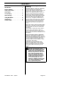
KEY TO SYMBOLS Checks and/or maintenance shall be carried out after having switched off the engine and disconnected the spark plug. X Cleaning at regular intervals is required. X Approved protective goggles or visor must be worn. X Approved protective goggles or visor, ear protection, and face mask in dusty environments must be worn. X WARNING! The blower can be dangerous! Careless or improper use can cause serious, even fatal injury.
SAFETY INSTRUCTIONS Personal safety equipment Muffler Persons who use the blower shall wear the following safety equipment: 1. Approved ear protection. 2. Approved eye protection. 3. Approved protective gloves. 4. Boots or work shoes with a non--slip sole. 5. Face mask when operating the blower in dusty environments. The muffler is designed to give the lowest possible noise level and to direct the engine’s exhaust fumes away from the operator.
SAFETY INSTRUCTIONS S Be careful, particularly if left hand operation is applied. Avoid any direct body contact with inlet cover area. Keep jewelry, loose clothing, or clothing with loosely hanging straps, ties, tassels, etc., away from inlet cover area. S Do not operate the blower while standing on a ladder or a stand. Other safety measures S Operate the blower only at reasonable hours, i.e. not early in the morning or late at night when people might be disturbed.
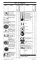
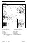
DESCRIPTION The blower 3 2 4 23 1 9 7 17 21 20 22 8 16 10 19 6 11 15 18 14 24 10 1. 2. 3. 4. 5. 6. 7. 8. 9. 10. 11. Shoulder strap (125BVX--SERIES) Throttle trigger STOP switch Variable speed control Fan housing Fuel cap Air filter Choke Primer bulb Inlet cover Vacuum handle (125BX--SERIES and 125BVX--SERIES) 12. Cutters (125BX--SERIES and 125BVX--SERIES) 545133423 Rev. 4 9/6/07 12 13 5 13. Fan impeller 14. Standard nozzle 15.
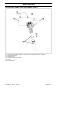
DESCRIPTION Accessories (125BX-- SERIES and 125BVX-- SERIES) 26 21 23 22 25 24 21. 22. 23. 24. 25. 26. Vacuum device with collection components consisting of items 22--26 below Collection bag tube Collection bag Vacuum tube in two sections Screw Shoulder strap 545133423 Rev.
DESCRIPTION Other equipment Safety equipment The following equipment on the blower is designed for protecting personnel and materials. These components should receive special attention whenever you operate, inspect and service the blower. Throttle trigger S The speed and the output of the engine are regulated by the throttle trigger (C). Stop switch S The stop switch (A) is used to stop the engine.
DESCRIPTION Ground wire S The ground wire (G) reduces static build--up during operation in dry conditions. G S The nozzles (L) have a bayonet mount for connection to the blower tube. Air is channeled through the blower tube to the nozzles, where the air discharge velocity increases and the air stream discharge pattern is formed to provide best performance.
DESCRIPTION Choke S The choke (Q) is located below the air filter cover and should be used every time the engine is cold--started. Q Adjusting the carburetor NOT FOR ALL MODELS S There are three adjusting screws (R) for adjusting the carburetor: S Low speed jet S High speed jet S Adjustment screw for idling S Adjusting the carburetor involves adapting the engine to local operating conditions, e.g. climate, altitude, gasoline and type of two--stroke engine oil used.
FUEL HANDLING Fuel mixture CAUTION! The machine is equipped with a two--stroke engine and must always be run using a mixture of petrol and two-stroke engine oil. It is important to accurately measure the amount of oil to be mixed to ensure that the correct mixture is obtained. When mixing small amounts of fuel, even small inaccuracies can drastically affect the ratio of the mixture. S Always start by filling half the amount of the gasoline to be used. Then add the entire amount of oil.
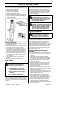
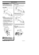
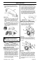
STARTING AND STOPPING Starting: Hold the body of the machine on the ground using your left hand (CAUTION! Not with your foot!). Firmly grip the starter rope handle with your right hand. DO NOT squeeze throttle trigger. Slowly pull out the cord until you feel some resistance (the starter pawls grip); then quickly and powerfully pull the cord. WARNING: Never wrap the starter cord around your hand. Min. 10 ft. (3 m) S Clean the area around the fuel cap. Contamination in the tank can cause operating problems.
USING THE BLOWER To blow away debris on the ground Fitting the blower tube and nozzle on the blower WARNING: When fitting the blower tube and nozzle, the engine must be switched off. The blower tube (T) has a pegged slot mounting system to the unit. To install or remove the blower tube (or collection bag tube for 125BVX--SERIES), the tube clamp bolt must be removed. Align slot in the blower air outlet with the raised rib on the tube and insert tube until the holes in the tube and housing align.
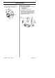
USING THE BLOWER WARNING: Never start the blower if the inlet cover is not closed, is damaged or cannot be closed (except if the vacuum tube is fitted). WARNING: Do not operate the blower while standing on a ladder or a stand. Start the blower as described in the Starting and Stopping section. Work according to the following instructions: 1. Never blow air toward fixed objects such as walls, large rocks, automobiles and fences. 2.
USING THE BLOWER Vacuuming Before vacuuming, put on the required safety equipment. WARNING: When working with the blower, wear the required personal safety equipment: 1. Hearing protection. 2. Eye protection. 3. Protective gloves. 4. Face mask in dusty environments. WARNING: Always check that the collection bag is intact and the zipper is closed before starting the blower. Never use a damaged bag. There is risk of injury due to flying debris. Be careful, particularly if left hand operation is applied.
MAINTENANCE Maintenance Safety The owner is responsible for the performance of all required maintenance as defined in the operator’s manual. Disconnect the spark plug before performing maintenance, except carburetor adjustments. X Carburetor Your Husqvarna product has been designed and manufactured to specifications that reduce harmful emissions. After the engine has used 8--10 tanks of fuel, the engine will be run--in.
MAINTENANCE Y Z AA BB WARNING: Mufflers fitted with catalytic converters get very hot during use and remain so for some time after stopping. This also applies at idle speed. Contact can result in burns to the skin. Remember the risk of fire! Air filter WARNING: Bear in mind that: Engine exhaust fumes contain carbon monoxide, which can cause carbon monoxide poisoning. For this reason you should not start or run the machine indoors, or anywhere that is poorly ventilated.
MAINTENANCE Weekly maintenance Spark plug The spark plug condition is influenced by: S Incorrect carburetor adjustment. S An incorrect fuel mixture (too much or incorrect type of oil). S Poor quality gasoline and/or oil S A dirty air filter. These factors cause deposits on the spark plug electrodes, which may result in operating problems and starting difficulties.
TECHNICAL DATA Technical data 125B Engine Cylinder volume, cm3 Cylinder bore, mm Stroke, mm Idle speed, rpm Max. speed - blowing, rpm: Max. speed - vacuuming, rpm: Max. engine output, acc.
TECHNICAL DATA Model 125B, 125BX--SERIES, 125BVX--SERIES Approved accessories Part. no. Gutter clean--out kit 952 711 918 Model 125BX--SERIES, 125BVX--SERIES Approved accessories Part. no. Vacuum kit 952 711 913 Model 125B Approved accessories Part. no. High velocity nozzle 545 119 501 DECLARATION OF CONFORMITY EC Declaration of Conformity (Only applies to Europe) We, Husqvarna Outdoor Products Italia, S.p.A., Valmadrera, Italy.