Operator’s Manual 125E Please read the operator’s manual carefully and make sure you understand the instructions before using the machine.
CONTENTS The Emissions Compliance Period referred to on the Emissions Compliance label indicates the number of operating hours for which the engine has been shown to meet Federal emissions requirements. Category C = 50 hours, B= 125 hours, and A = 300 hours. Contents CONTENTS Contents . . . . . . . . . . . . . . . . . . . . . . . . 2 Note the following before starting . . . . 2 KEY TO SYMBOLS Symbols . . . . . . . . . . . . . . . . . . . . . . . . . 3 SAFETY INSTRUCTIONS Personal protective equipment . . .
KEY TO SYMBOLS Symbols Arrows which show limits for handle positioning. WARNING: This edger can be dangerous! Careless or incorrect use can result in serious or fatal injury to the operator or others. Always wear approved protective gloves. Please read the operator’s manual carefully and make sure you understand the instructions before using the machine. Wear sturdy, non--slip boots. Other symbols/decals on the machine refer to special certification requirements for certain markets.
SAFETY INSTRUCTIONS Personal protective equipment FIRST AID KIT Always have a first aid kit nearby. IMPORTANT! Whenever you use a lawn edger, you must wear personal protective equipment that is approved by the authorities. Personal protective equipment does not eliminate the risk of accidents, but it can reduce the effects of an injury in the event of an accident. Ask your dealer for help when choosing protective equipment.
SAFETY INSTRUCTIONS WARNING: Mufflers fitted with catalytic converters get very hot during use and remain so for some time after stopping. This also applies at idle speed. Contact can result in burns to the skin. Remember the risk of fire! Cutting attachment guard This guard is intended to prevent loose objects from being thrown towards the operator. The guard also protects the operator from accidental contact with the cutting attachment.
SAFETY INSTRUCTIONS Throttle lock Stop switch S Make sure the throttle control is locked at the idle setting when the throttle lock is released. S Start the engine and make sure the engine stops when you push and hold the stop switch. Cutting attachment guard S Press the throttle lock and make sure it returns to its original position when you release it. S Ensure that the guard is undamaged and is not cracked.
SAFETY INSTRUCTIONS Cutting equipment Locking nut This section describes how to choose and maintain your cutting equipment in order to: S Obtain maximum cutting performance. S Extend the life of cutting equipment. General rules: S Protect your hand from injury during assembly. Always wear protective gloves. Use the blade guard as protection when tightening nut. Tighten the nut by turning against the direction of rotation. Loosen the nut by turning in the direction of rotation.
SAFETY INSTRUCTIONS Personal protection General safety precautions IMPORTANT! S The machine is only designed for cutting the edges of lawns. S The only accessories you can operate with this engine unit are the cutting attachments we recommend in the “Technical data” section. S Never use the machine if you are tired, if you have drunk alcohol, or if you are taking medication that could affect your vision, your judgment or your coordination.
SAFETY INSTRUCTIONS S Check that the blade and blade guard are correctly secured. S When adjusting the carburetor, make sure the blade is held against the ground and that no one is in the immediate vicinity. S Make sure the blade does not rotate when idling. S Make sure the handle and safety features are in order. Never use a machine that has parts missing or has been changed in relation to the specification. S Only use the machine for the purpose for which it was intended.
SAFETY INSTRUCTIONS S Always drop to idling speed after each working operation. Longer periods running at full throttle without loading the engine (that is without resistance, which the engine feels from the blade when edging) can lead to serious engine damage. S It is recommended that the engine not be operated for longer than 1 minute at full throttle. S Be especially careful when pulling the edger towards you during work. S If heavy vibrations occur, stop the engine.
SAFETY INSTRUCTIONS Safety instructions after completing work S Ensure the blade has stopped before cleaning, making repairs or an inspection. Remove the spark plug cable from the spark plug. S Wear heavy--duty gloves when making repairs to the edger. S Store the machine out of reach of children. S Only use original spare parts during repair.
KNOW YOUR EDGER 4 1 6 3 10 2 8 11 9 5 16 4 7 15 13 20 14 12 1 18 19 17 3 Know your edger 1. 2. 3. 4. 5. 6. 7. 8. 9. 10. 11. Blade Grease filler cap Bevel gear Blade guard Shaft Loop handle Throttle control Stop switch Throttle lock Cylinder cover Starter handle 12. 13. 14. 15. 16. 17. 18. 19. 20. 21. 22.
ASSEMBLY NOTE: Make sure unit is assembled correctly as shown in this manual. Assembling the loop handle S Position the handle on the shaft. Note that the handle must be mounted between the two arrows on the shaft. A 3. While holding the screwdriver in position, remove locking nut by turning clockwise. 4. Remove both washers (C and D) and the blade (B) from the output shaft. S Fit the screw, securing plate and wing nut as shown in the diagram. S Tighten the wing nut. B C D Assembling the blade E 5.
FUEL HANDLING Fuel mixture CAUTION! The machine is equipped with a two--stroke engine and must always be run using a mixture of gasoline and two-stroke engine oil. It is important to accurately measure the amount of oil to be mixed to ensure that the correct mixture is obtained. When mixing small amounts of fuel, even small inaccuracies can drastically affect the ratio of the mixture. S Always start by flling half the amount of the gasoline to be used. Then add the entire amount of oil.
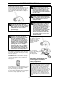
STARTING AND STOPPING Cold engine Check before starting Primer bulb: Press the primer bulb 10 times until fuel begins to fill the bulb. The primer bulb need not be completely filled. S Inspect the unit before each use. Replace damaged parts. Check for fuel leaks. Make sure all fasteners are in place and secure. Make sure the blade and blade guard are properly installed and the blade nut is securely tightened. S Check that the blade and blade guard are not damaged or cracked.
STARTING AND STOPPING Warm engine With a warm engine, squeeze and hold the throttle trigger. Pull starter rope sharply while squeezing throttle trigger until engine runs. Stopping Stop the engine by pushing and holding the stop switch in the STOP position until the engine stops. WARNING: When the engine is started with the choke in the closed position the cutting attachment will start to rotate immediately.
MAINTENANCE The owner is responsible for the performance of all required maintenance as defined in the operator’s manual. Carburetor The idle speed is correctly adjusted when the engine will run smoothly in every position. The idle speed should also be well below the speed at which the cutting attachment starts to rotate. Your Husqvarna product has been designed and manufactured to specifications that reduce harmful emissions. After the engine has used 8--10 tanks of fuel, the engine will be run--in.
MAINTENANCE 0.024s (0.6 mm) Muffler bolts CAUTION! Never use a machine that has a faulty or loose muffler. Ensure the muffler bolts are tight. Air filter WARNING: Mufflers fitted with catalytic converters get very hot during use and remain so for some time after stopping. This also applies at idle speed. Contact can result in burns to the skin. Remember the risk of fire! WARNING: The inside of the muffler contain chemicals that may be carcinogenic.
MAINTENANCE Maintenance schedule The grease in the bevel gear does not normally need to be changed except if repairs are carried out. Below you will find some general maintenance instructions. Adjusting the edger’s cutting depth Daily maintenance S Check throttle trigger and throttle trigger lockout function. S Check that the stop switch works correctly. S Check that there are no fuel leaks from the engine, tank or fuel lines. S Check that the blade does not rotate when the engine is idling.
TECHNICAL DATA Technical data 125E Engine Cylinder volume, cu.in./cm3 Cylinder bore, inch/mm Stroke, inch/mm Idle speed, rpm Recommended max. speed, rpm Speed of output shaft, rpm Max. engine output, acc.
WARRANTY STATEMENT SECTION 1: LIMITED WARRANTY THESE PRODUCTS EXCEPT TO THE EXTENT PROHIBITED BY APPLICABLE LAW. ANY IMPLIED WARRANTY OR MERCHANTABILITY OR FITNESS FOR A PARTICULAR PURPOSE ON THESE PRODUCTS IS LIMITED IN DURATION TO THE WARRANTY PERIOD AS DEFINED IN THE LIMITED WARRANTY STATEMENT. HUSQVARNA RESERVES THE RIGHT TO CHANGE OR IMPROVE THE DESIGN OF THE PRODUCT WITHOUT NOTICE, AND DOES NOT ASSUME OBLIGATION TO UPDATE PREVIOUSLY MANUFACTURED PRODUCTS.
U.S. EPA / CALIFORNIA / ENVIRONMENT CANADA EMISSION CONTROL WARRANTY STATEMENT YOUR WARRANTY RIGHTS AND OBLIGATIONS: WARRANTY COMMENCEMENT DATE: The U.S. Environmental Protection Agency, California Air Resources Board, Environment Canada and HUSQVARNA are pleased to explain the emissions control system warranty on your year 2005 and later small off--road engine. In California, all small off--road engines must be designed, built, and equipped to meet the State’s stringent anti--smog standards.
U.S. EPA / CALIFORNIA / ENVIRONMENT CANADA EMISSION CONTROL WARRANTY STATEMENT MAINTENANCE, REPLACEMENT AND REPAIR OF EMISSION RELATED PARTS: EMISSION CONTROL WARRANTY PARTS LIST: Any HUSQVARNA approved replacement part used in the performance of any warranty maintenance or repair on emission related parts will be provided without charge to the owner if the part is under warranty. MAINTENANCE STATEMENT: Carburetor, Ignition System: Spark Plug (covered up to maintenance schedule), Ignition Module.